6. Limon™ BMS Software Pack Status
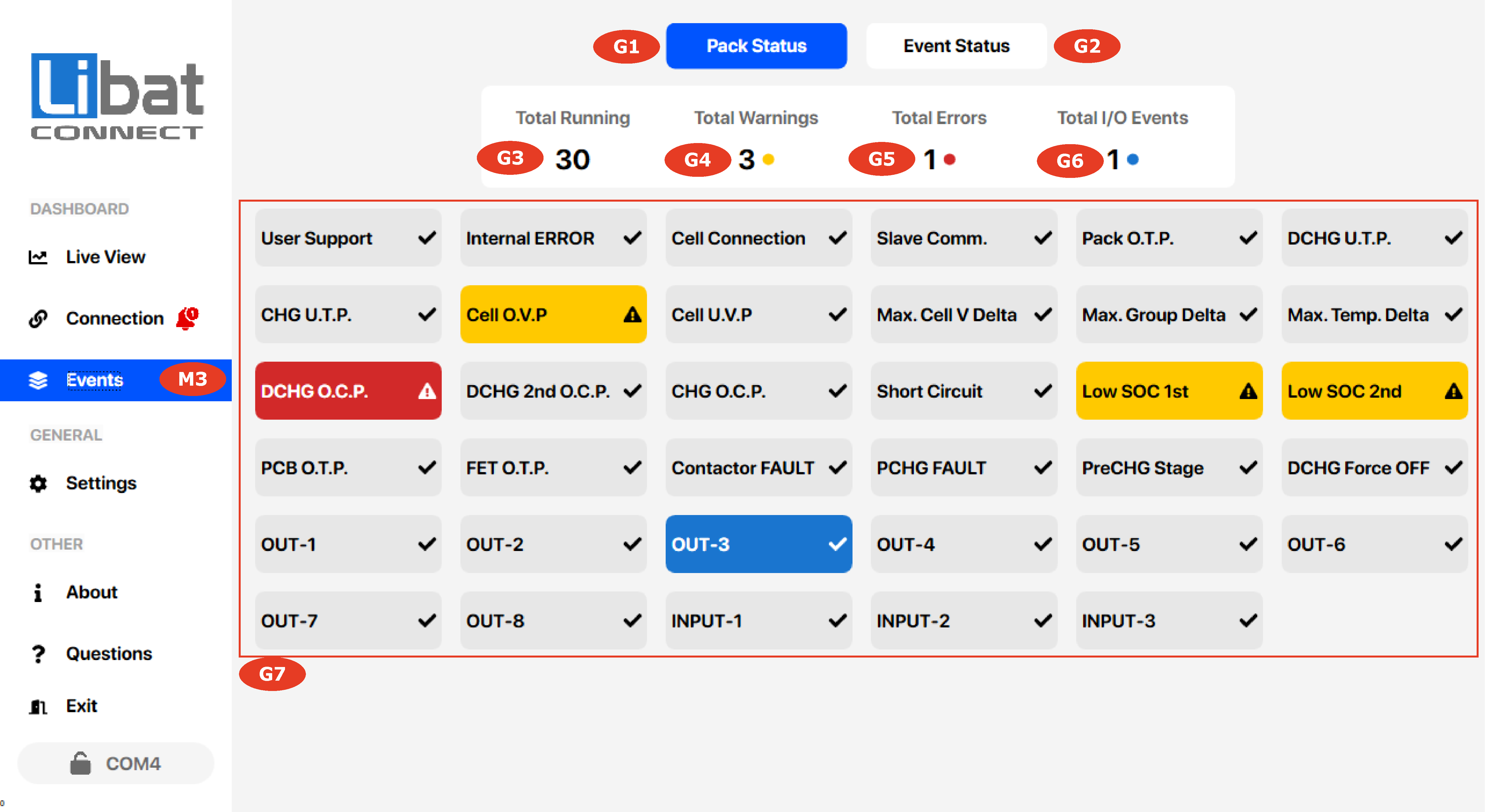
For a stable battery system, you always must care about system status and watch the events. Especially, setting up the battery management system first time, you must sure about the setttings. This screen gives you ideas about, what is going on inside the battery.
Fig.6.1.1: Pack Status Screen

Tip
You will see a small description of related event when hover your mouse on items.
Table.6.1.1: Screen Elements Descriptions
| Field No. | Description |
|---|---|
| M3 | Selection tab for Events. |
| G1 | Pack Status TAB. |
| G2 | Event Status TAB. |
| G3 | Total number of normally running events. |
| G4 | Total number of warnings. |
| G5 | Total number of errors. |
| G6 | Total number of activated input/outputs. |
| G7 | All system events. Hover mouse for the event details. |
Table.6.1.2: Events Descriptions (Refer the Fig.6.1)
| Event Name | Event Type | Description | Troubleshoot Suggestion |
|---|---|---|---|
| User Support | CRITICAL ERROR | Critical error(s) has occured | User must resolve the problem and reset the system |
| Internal EERROR | CRITICAL ERROR | Something went wrong about HW or SW level | Contact to support |
| Cell Connection | ERROR | Detected cell count and setting mismatch | Check "Module Settings" |
| Slave Comm. | ERROR | Slave Module Communication Error | Check "Module Settings" and cable connections |
| Pack O.T.P. | ERROR, WARNING | Over Temperature Protection | Protection limit should set to correct value |
| DCHG U.T.P. | ERROR, WARNING | Discharge Under Temperature Protection | Protection limit should set to correct value |
| CHG U.T.P. | ERROR, WARNING | Charge Under Temperature Protection | Protection limit should set to correct value |
| Cell O.V.P. | ERROR, WARNING | Cell Over Voltage Warning or Protection | Limits should set to correct value |
| Cell U.V.P. | ERROR, WARNING | Cell Under Voltage Warning or Protection | Limits should set to correct value |
| Max. Cell V Delta | CRITICAL ERROR | Maksimum Cell Unbalanced Voltage Protection | Check "Cell Settings" |
| Max. Group Delta | CRITICAL ERROR | Paralel Pack Voltage Delta Exceed | Check "Cell Settings" |
| Max. Temp. Delta | CRITICAL ERROR | Maksimum Allowed Temperature Measurement Difference | Check "Temperature Settings" |
| DCHG O.C.P. | ERROR | Discharge Over Current Protection Point 1 | Check "Current Settings" |
| DCHG 2nd O.C.P. | ERROR | Discharge Over Current Protection Point 2 | Check "Current Settings" |
| CHG O.C.P. | ERROR | Charge Over Current Protection | Check "Current Settings" |
| Short Circuit | CRITICAL ERROR | Too High Level Current Detection | Check "Current Settings" |
| Low SOC 1st | WARNING | Low State of Charge Warning Point 1 | - |
| Low SOC 2nd | WARNING | Low State of Charge Warning Point 2 | - |
| PCB O.T.P. | ERROR | PCB Over Temperature Protection | Check "Temperature Settings" |
| FET O.T.P. | ERROR | FET Over Temperature Protection | Check "Temperature Settings" |
| Contactor FAULT | CRITICAL ERROR | Maincontactor Malfunction | Check Contactor Terminal Voltages |
| PCHG FAULT | ERROR | Precharge Fault due to settings | Check PCHG settings and PCHG path current |
| PreCHG Stage | FUNCTIONAL STATE | Indication of Precharge Stage is active or not | |
| DCHGForce OFF | FUNCTIONAL STATE | Indication of DCHG path force to OFF | |
| OUT-1 | I/O STATE | Output No#1 State | See specific BMS page for output details |
| OUT-2 | I/O STATE | Output No#2 State | See specific BMS page for output details |
| OUT-3 | I/O STATE | Output No#3 State | See specific BMS page for output details |
| OUT-4 | I/O STATE | Output No#4 State | See specific BMS page for output details |
| OUT-5 | I/O STATE | Output No#5 State | See specific BMS page for output details |
| OUT-6 | I/O STATE | Output No#6 State | See specific BMS page for output details |
| OUT-7 | I/O STATE | Output No#7 State | See specific BMS page for output details |
| OUT-8 | I/O STATE | Output No#8 State | See specific BMS page for output details |
| INPUT-1 | I/O STATE | INPUT 1 ENABLE/DISABLE State | See specific BMS page for input details |
| INPUT-2 | I/O STATE | INPUT 2 ENABLE/DISABLE State | See specific BMS page for input details |
| INPUT-3 | I/O STATE | INPUT 3 ENABLE/DISABLE State | See specific BMS page for input details |