7.1 Limon™ BMS Software Module Settings
Battery management system's most important part is the settings. User must set the correct parameters of the system to achieve no errors.
Danger
Always double check your settings before saving all settings.
Fig.7.1.1: Module Settings Screen
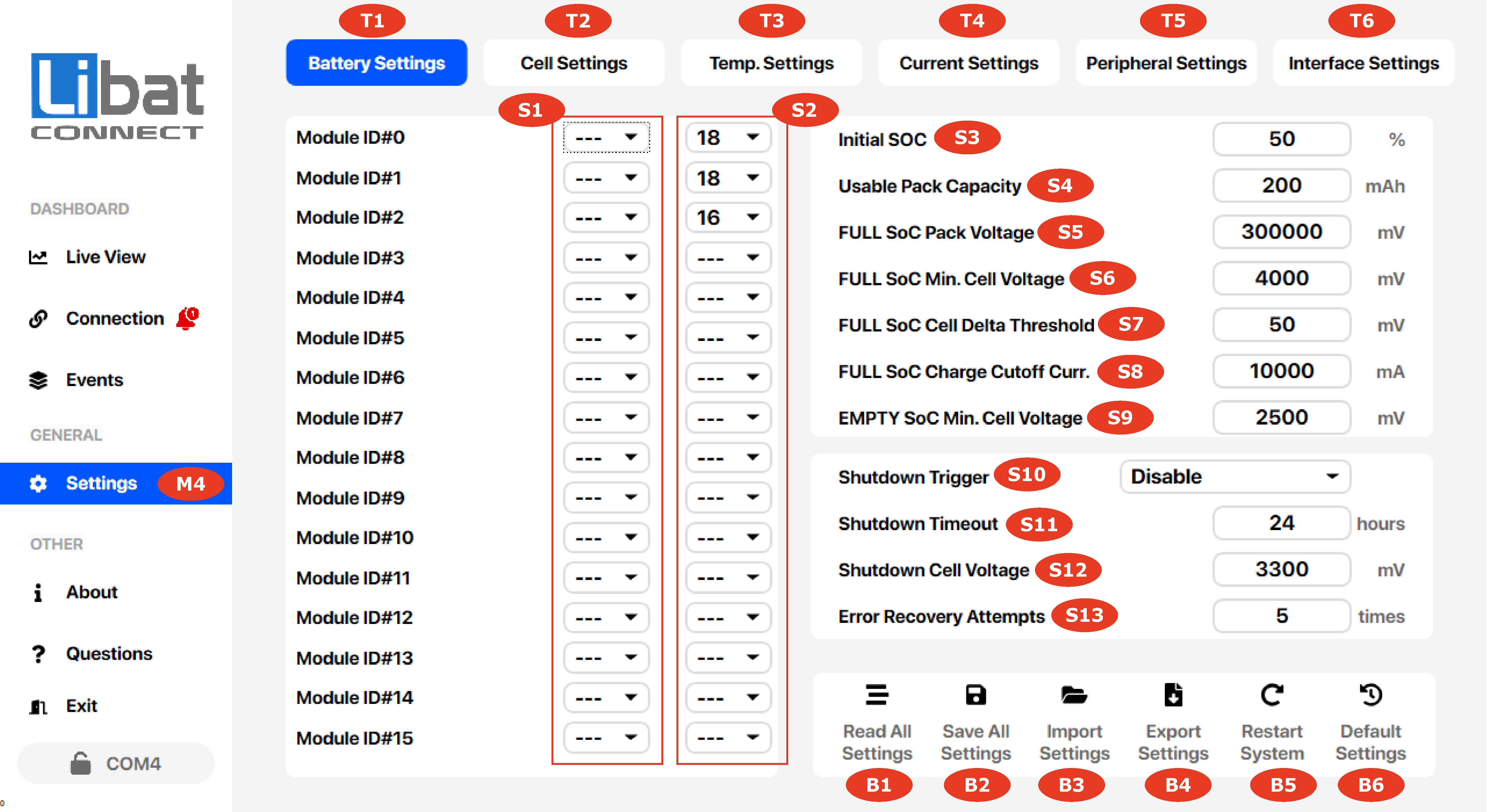
Table.7.1.1: Module Settings Screen Elements Descriptions
| Element No. | Description | Setting Options |
|---|---|---|
| M4 | Selection tab for Settings. |
|
| T1 | Selection tab for Battery Settings. |
|
| S1 | Parallel group number selection. Select same group number for arranging parallel batteries | Options PG1-PG6. Up to 6 packs can be arrange in paralel. Leave it disabled for normal operation. |
| S2 | Module cell count settings starting from ID#0 to ID#15. Select correct number of cell for every module ID. | Select cell between 4-18 cells |
| S3 | Initial SOC of Battery Pack. | Set for initial percentage of battery at a moment. Setting another value than before will update SOC value. |
| S4 | Battery usable capacity in mAh unit. 40Ah = 40000mAh | Set capacity to the correct value before setting initial SOC. |
| S5 | Full SOC pack voltage for recalibration to %100 | Set minimum pack voltage for triggering to set SOC to full. After reaching voltage point, other conditions must follow. |
| S6 | Minumum cell voltage for recalibration SOC to %100 | Set minimum cell voltage for triggering to set SOC to full. All cells must be equal or higher than this voltage. |
| S7 | Maxsimum cell delta voltage threshold between any cell. | Set maksimum cell voltage delta for triggering to set SOC to full. |
| S8 | Cutoff current before recalibration SOC to %100. | After meeting other conditions, charge current must be as low as that value. |
| S9 | Maximum cell delta voltage threshold for recalibration SOC to %0. | Any cell voltage under this value will trigger SOC to set %0. |
| S10 | Shutdown Trigger Options List Below: Disable: No Sleep Sleep Timeout: System Sleep After Sleep Timeout Value Shipping Mode: Force System Into Sleep After 10 mins Critical Cell Voltage: Put System Into Sleep If Any Cell Voltage is Below "Critical Min. Cell Voltage" Value Timeout or Critical: Put System Into Sleep If Either Sleep Timeout or Critical Cell Voltage Occurred |
Choose shutdown trigger event carefully. Any incompatible setting will put BMS into shutdown loop. |
| S11 | Shutdown timeout value for trigger shutdown event. | Any battery situation except IDLE will reset timer value. |
| S12 | Minumum Cell Voltage for trigger shutdown event. | Any cell value under this value will trigger shutdown according to shutdown trigger selection. |
| S13 | Error recovery retry times before user attention required event. | If set to 0, disables retry limit and system will try to recover forever any error situation. This may cause to lower lifecycle of power path switching elements or exceeding voltage limits. Retry cycle has hysteresis to detect and recover. |
| B1 | Read all setting from BMS memory. | You must read all the settings from BMS before making changes on the any settings. |
| B2 | Save all setting to BMS memory. | You must save all the settings after making changes on the any settings. |
| B3 | Import setting from setting file on your local computer. | You can import settings which exported before. |
| B4 | Export setting to setting file on your local computer. | You can export settings after read all event. |
| B5 | Restart the BMS board | Some changes may active after a software restart event. |
| B6 | Turn BMS into factory settings. | This event cannot be undone. |