7.5 Limon™ BMS Software Peripheral Settings
Battery management system's most important part is the settings. User must set the correct parameters of the system to achieve no errors.
Danger
Always double check your values before saving all settings.
Fig.7.5.1: Peripheral Settings Screen
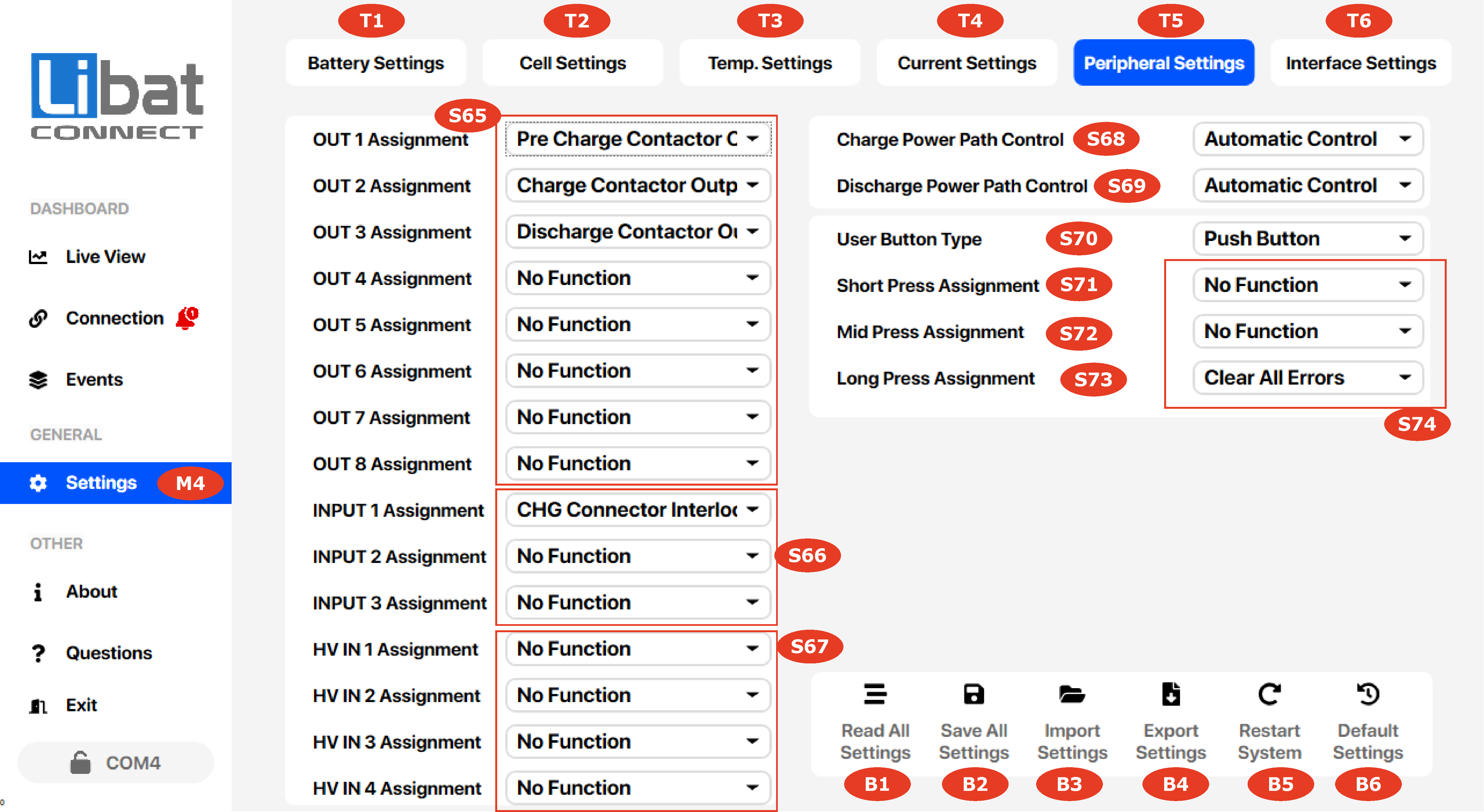
Table.7.5.1: Peripheral Settings Screen Elements Descriptions
| Element No. | Description | Setting Options |
|---|---|---|
| M4 | Selection tab for Settings. |
|
| T5 | Selection tab for Peripheral Settings. |
|
| S65 | Output function assignment for defined outputs | Assign a function for specific output. See the BMS model page for output physical situation and number like relay, ttl output or open drain. No Function: No state Change in Any Condition Low SOC Limit-1(≥15): Output stays active while SOC below %15 Low SOC Limit-2(≥5): Output stays active while SOC below %5 Over Temperature Warning: Output stays active if any temperature warning occurred Cell Over Voltage Warning: Output stays active if any cell warning occurred External Led Functionality: Output state acts same with external led state Main Concactor Output: Main contactor control output for power path control Pre Charge Concactor Output: Output for pre charge control circuitary Always ON: Output stays always ON Charge Contactor Output: Output signal for charge power path control only Discharge Contactor Output: Output signal for discharge power path control only |
| S66 | Input function assignment for defined inputs | Assign a function for specific input. See the BMS model page for input physical situation and number. No Function: No State Change in Any Condition Main Contactor Auxiliary: Input For Main Contactor's Auixilary Output Battery Output Disable: Force battery power path(s) to OFF DCHG Power Path Disable: Force battery DCHG power path to OFF CHG Connector Interlock: Interlock input to detect charge connector whether connected or not |
| S67 | HV voltage detection input | Detect and measure high voltage points to ensure HV path health. |
| S68 | Charge power path override control | For testing purposes, override the status of BMS charge power path |
| S69 | Discharge power path override control | For testing purposes, override the status of BMS discharge power path |
| S70 | User button type options: Push Button : Standart Push Button On/Off Switch: Standart 2 Position On/Off Switch |
Short-mid-long press actions are only available when push button option is selected. On/Off Switch option blocks board shutdown. |
| S71 | Short Press Assigment Options | Any press time between (1 second < Push Time < 5 seconds ) will active short press action. Click once more to approve short press action after holding proper time. |
| S72 | Mid Press Assigment Options | Any press time between ( 5 seconds < Push Time < 10 seconds ) will active mid press action. Click once more to approve mid press action after holding proper time. |
| S73 | Long Press Assigment Options | Any press time more than ( 10 seconds < Push Time ) will active long press action. Click once more to approve long press action after holding proper time. |
| S74 | Press Assigment Options | Any assignment can be activated after one single press by holding certain of time needed Restart System : Restarts System same as Power Up Clear All Errors: Clears All Erros and forces the power outputs ON along 60 seconds Shutdown Board: Shutdowns the system for minimize the power consumption. Sleep Board: System goes to the sleep asap and ready to wakep up via Canbus or User button. This option does not guarentee the minimize consumption. |
| B1 | Read all setting from BMS memory. | You must read all the settings from BMS before making changes on the any settings. |
| B2 | Save all setting to BMS memory. | You must save all the settings after making changes on the any settings. |
| B3 | Import setting from setting file on your local computer. | You can import settings which exported before. |
| B4 | Export setting to setting file on your local computer. | You can export settings after read all event. |
| B5 | Restart the BMS board | Some changes may active after a software restart event. |
| B6 | Turn BMS into factory settings. | This event cannot be undone. |