4. BMS1810 Battery Connection
BMS1810 is designed for between 5S to 18S high end battery systems. However, user need to arrange signal and power cables for various series of battery pack. In this section, you can find the connection diagrams for 5S to 18S battery packs.
4.1 Power-Up Sequence
BMS1810 able to get its own power from power connector. Power input suitable for 15V to 80V voltage sources. Up tp 18S batteries can connect directly to the BMS power input or external power source could be used. For the first setup, power input must be connected first rather than cell inputs. After first connection, user may need to press user button to wake up board.
Danger
Always make sure power source GND connection (connector No#14) is made properly and connected before any cell connection. Don't connect any cell before main power source connection. Never leave alone BMS without proper GND connection. (refer to Connector no#14 GND pin)
4.2 Cell Connection
Info
User may arrange the shorted pins either on the cell measurement cable or jumpers on the board. Its up to user choice. For all type of connections, it is very important to short unused pins to highest cell of the battery pack for high quality measurements.
Fig.4.2.1: BMS1810 5S to 18S Battery Cell Connections
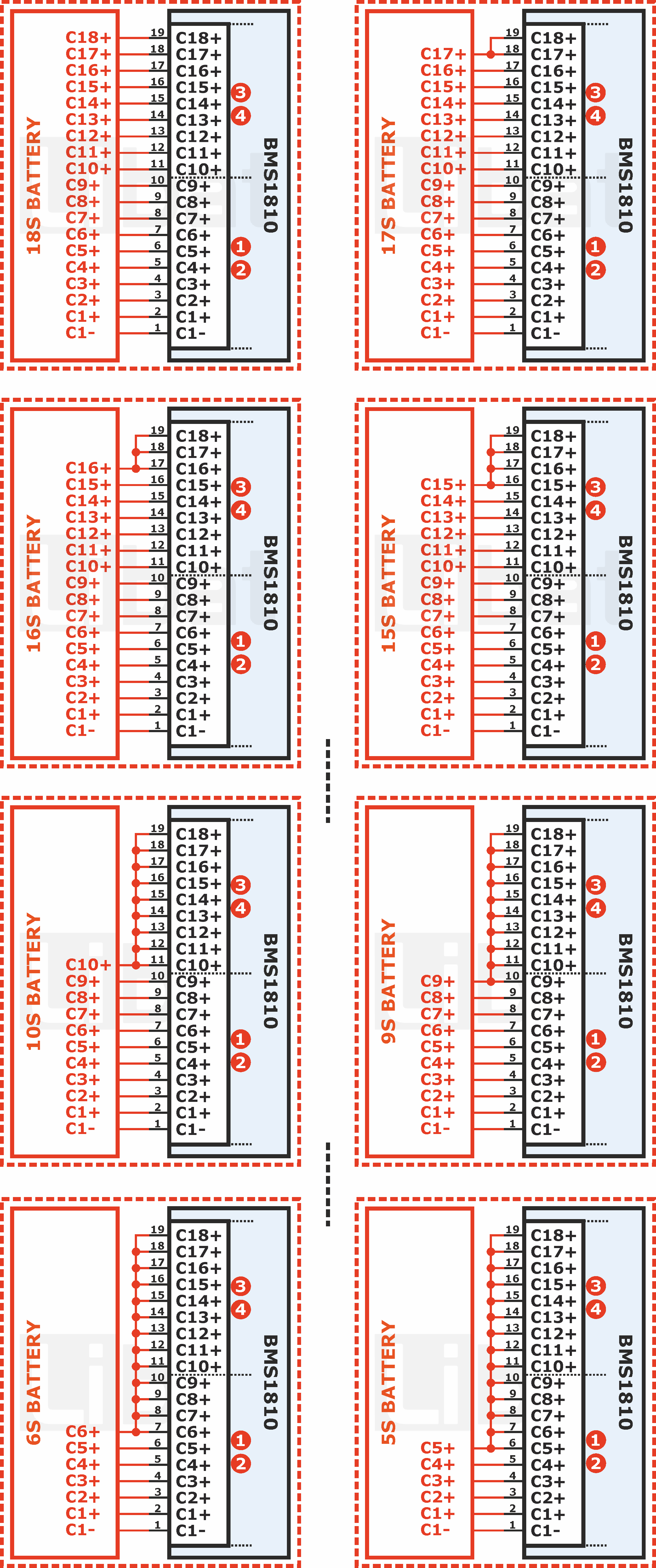
Tip
BMS1810 automatically detects how many cells connected to the board on power-up sequence. Reset after cell connection and see the connected cell count from PC software. If something goes wrong, try to fix the cables.
4.3 Temperature Sensor Connection
Fig.4.3.1: BMS1810 Temperature Sensor Connection
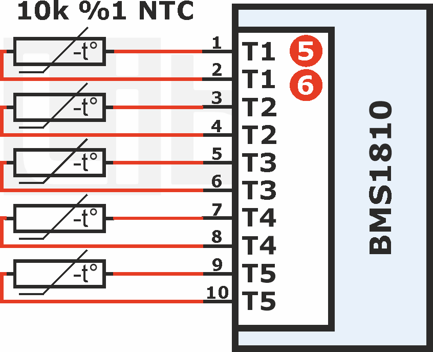
Tip
BMS1810 automatically detects how many temperature sensors connected to the board on power-up sequence. Unused pins shall short or leave float.