7.4 Limon™ BMS Software Current Settings
Battery management system's most important part is the settings. User must set the correct parameters of the system to achieve no errors.
Danger
Always double check your values before saving all settings.
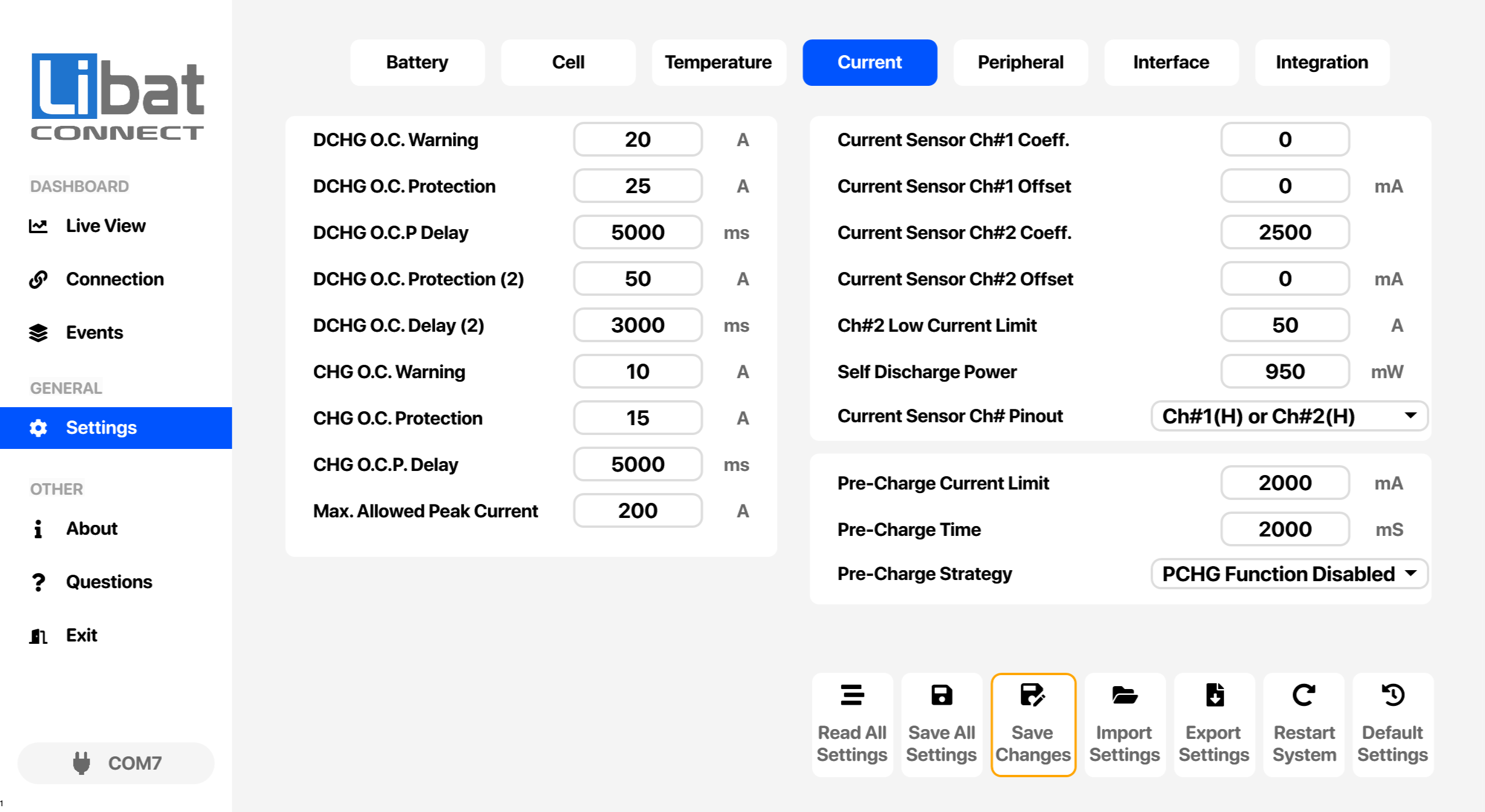
Table.7.4.1: Current Settings Screen Elements Descriptions
| No. | Description | Setting Options |
|---|---|---|
| T4 | Selection tab for Current settings. |
|
| M4 | Selection tab for Settings. |
|
| S46 | Discharge Over Current Warning | Triggers a warning event before reaching discharge over current protection point. See Current Limits in the User Manual. |
| S47 | Discharge Over Current Protection (1st) | First limit for maximum allowed discharge current. This value may set to lower than 2nd point with higher delay time. Slow acting current limit. See Current Limits in the User Manual. |
| S48 | Discharge Over Current Protection Delay (1st) | Delay time before 1st discharge over current protection event. See Current Limits in the User Manual. |
| S49 | Discharge Over Current Protection (2nd) | Second limit for maximum allowed discharge current. This value may set to higher than 1st point with lower delay time. Fast acting current limit. See Current Limits in the User Manual. |
| S50 | Discharge Over Current Protection Delay (2nd) | Delay time before 2nd discharge over current protection event. See Current Limits in the User Manual. |
| S51 | Charge Over Current Warning | Triggers a warning event before reaching charge over current protection point. See Current Limits in the User Manual. |
| S52 | Charge Over Current Protection | Maximum allowed charge current. See Current Limits in the User Manual. |
| S53 | Charge Over Current Protection Delay | Delay time before charge over current protection event. See Current Limits in the User Manual. |
| S54 | Maximum Allowed Peak Current | Very fast acting discharge current limit. Assume this value as the highest discharge current threshold without any delay time. See Current Limits in the User Manual. |
| S55 | Current Sense Input Channel No 1 Coefficient | Voltage to Current Coefficient for channel 1 input (sensor output) See Current Measurement in the User Manual. |
| S56 | Current Sense Input Channel No 1 Offset | Negative or positive current offset can be set when needed. See Current Measurement in the User Manual. |
| S57 | Current Sense Input Channel No 2 Coefficient | Voltage to Current Coefficient for channel 2 input (sensor output) See Current Measurement in the User Manual. |
| S58 | Current Sense Input Channel No 2 Offset | Negative or positive current offset can be set when needed. See Current Measurement in the User Manual. |
| S59 | Current Sense Input Channel 2 Low current limit | If two channel current sensor type used in the system, low current channel current value can be set. Otherwise this value is not effective to current sensing. See Current Measurement in the User Manual. |
| S60 | Self Discharge Power | Constant consumption of the BMS and of every load that does not pass through the current sensor. The state of charge counts it, also at rest. See Current Measurement in the User Manual. |
| S61 | Current sensor configuration and pinout setting | You can select various type of current sensor and channel configuration. For best measurement result select correct type. NO SENSOR INSTALLED: No sensor was installed to battery pack. Ch#1(H) or Ch#2(H): Default. Select when one channel sensor is used. Set one or two channel's coefficient. If any channel can't use, leave it floating, set coefficient to zero (0) and set only used channel's coefficient. Ch#1(H) and Ch#2(L): Select when two channel sensor is used. Set every channel's coefficient for both low and high current side. Measurement channel is switch internally according to settings. Ch#1(L) and Ch#2(H): Same as Ch#1(H) and Ch#2(L) with the channels swapped, so Ch#1 is the low current side and Ch#2 is the high current side. Select when the sensor is wired the other way round. Canbus Current Sensor: TBD. See Current Measurement in the User Manual. Options: NO SENSOR INSTALLED, Ch#1(H) or Ch#2(H), Ch#1(H) and Ch#2(L)*, Ch#1(L) and Ch#2(H) |
| S62 | Precharge current limit | The precharge ends early as soon as the current falls below this value. If the current is still at or above it when the Pre-Charge Time runs out, the BMS sets Pre-Charge Fault. See Precharge in the User Manual. |
| S63 | Precharge time | Precharge time before discharge power path is switching to ON. See Precharge in the User Manual. |
| S64 | Precharge Strategy | You can enable precharge process and precharge conditions. PCHG Function Disabled: No precharge event. System will switch ON the DCHG path without precharge ptogress. PCHG Time Only: System will apply precharge current along PCHG time before DCHG path is switching ON. PCHG Time and Current Limit: System will apply precharge current along PCHG time and checks PCHG path current before DCHG path is switching ON. See Precharge in the User Manual. Options: PCHG Function Disabled, PCHG Time Only, PCHG Time and Current Limit |
Settings buttons
The buttons at the bottom of this screen are explained in 7.8 Settings Buttons.