3. RLY200 Connection
RLY200 turns an output of a LiBat™ BMS into a relay contact. This page shows how the two relays are switched on the board and which BMS outputs can switch it.
3.1 Block Diagram
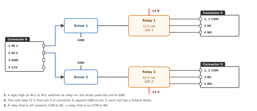
RLY200 has two relays with a 12 V coil. A high level on IN-1 or IN-2 on connector 6 makes the driver of that relay pull its coil to GND, and the relay switches on. A flyback diode sits across each coil, and the LED of the relay (LED 3 for relay 1, LED 2 for relay 2) is on while the relay is on. The contact of relay 1 is on connector 4, that of relay 2 on connector 5.
Fig.3.1.1: RLY200 Block Diagram
3.2 Supply
The relay coils take 12 V on pin 4 of connector 6, against GND on pin 3. Connector 1 is not used: leave it unconnected. A 5 V supply, such as ISO 5V of a BMS, is too low for the coils.
3.3 Connection to a BMS Output
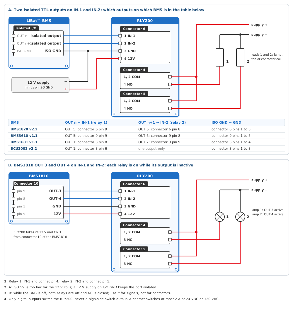
The RLY200 is switched by the digital outputs of a LiBat™ BMS on connector 6: IN-1 switches relay 1 (contact on connector 4), IN-2 switches relay 2 (contact on connector 5). Fig.3.3.1 uses both relays. The pinout page of each LiBat™ board lists its outputs with the LiMon™ OUT number that drives them.
- Isolated TTL outputs (BMS1820 and BMS3610 OUT 5 and OUT 6, BMS1601 OUT 1 and OUT 2; BCU2002 has one, OUT 1): on IN-1 and IN-2, with ISO GND on GND. Each relay is on while its output is active. Supply the RLY200 from a separate 12 V supply whose minus is on ISO GND, so that the isolated port stays isolated from the BMS.
- BMS1810 OUT 3 and OUT 4 (open collector, 10 kΩ to 12 V): on IN-1 and IN-2, with 12 V and GND from connector 10 of the BMS1810. Each relay is on while its output is inactive, so use NC for a circuit that must close while the output is active. While the BMS is off, both relays are off and NC is closed: use this for signals, not for contactors.
Fig.3.3.1: RLY200 Connection Examples
Not for high-side outputs
Do not connect a high-side switch output (BMS1820 and BMS3610 OUT 1 to OUT 4, BCU2002 OUT 2 to OUT 5, BMS1810 OUT 1 and OUT 2) to IN-1 or IN-2: the input resistor of the RLY200 is not made for 12 V and can be damaged. These outputs drive a mini relay directly.
Warning
Do not switch more than 2 A at 24 VDC or 120 VAC through a relay contact. Switch a larger load through a contactor.
Danger
Check every connection and cable before you plug a connector into the RLY200 or the BMS.