2. BMS3610 Pinouts and Descriptions
BMS3610 measures up to 36 cells as two modules: cells 1 to 18 (Module ID#0) on connector 2 with their temperature sensors on connector 1, and cells 19 to 36 (Module ID#1) on connector 5 with their temperature sensors on connector 4. It drives the slave modules over the isolated daisy chain (RJ45 connector 7 or 4-pin connector 6). Power and the button come in on connectors 16 and 17, the current sensor on connector 3, the communication ports on connectors 10 and 11, and the inputs and outputs on connectors 8, 9 and 15. Arrange the cables with the pinouts below; a number in the figures opens the table of that connector.
Danger
Check every connection and cable before you plug a connector into the BMS3610. Connectors 4 and 5 are at the potential of the upper half of the pack, up to the full pack voltage above B-.
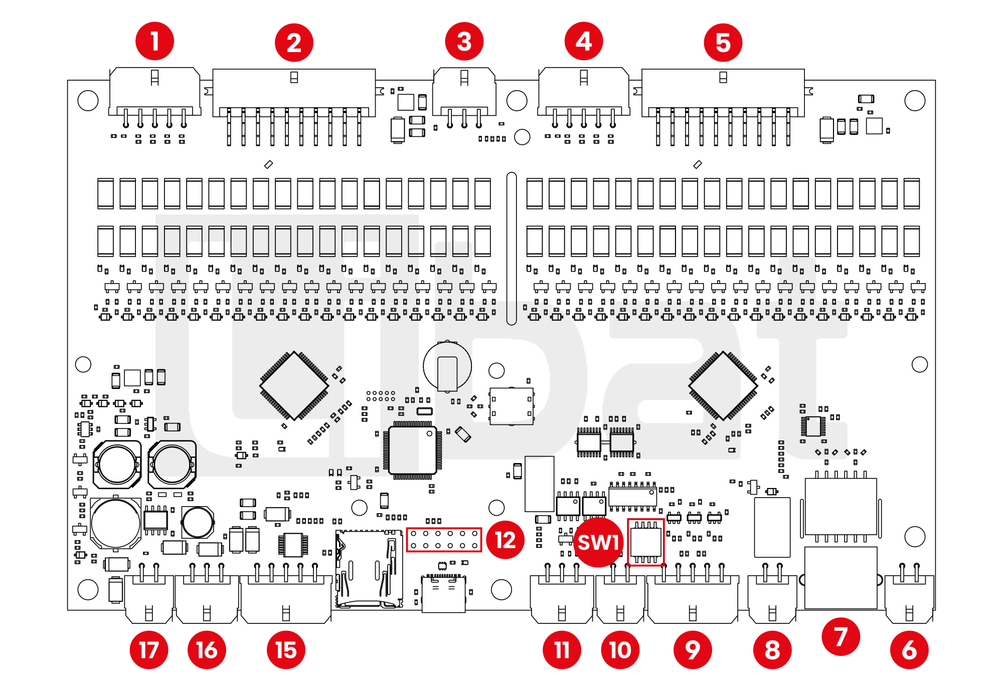
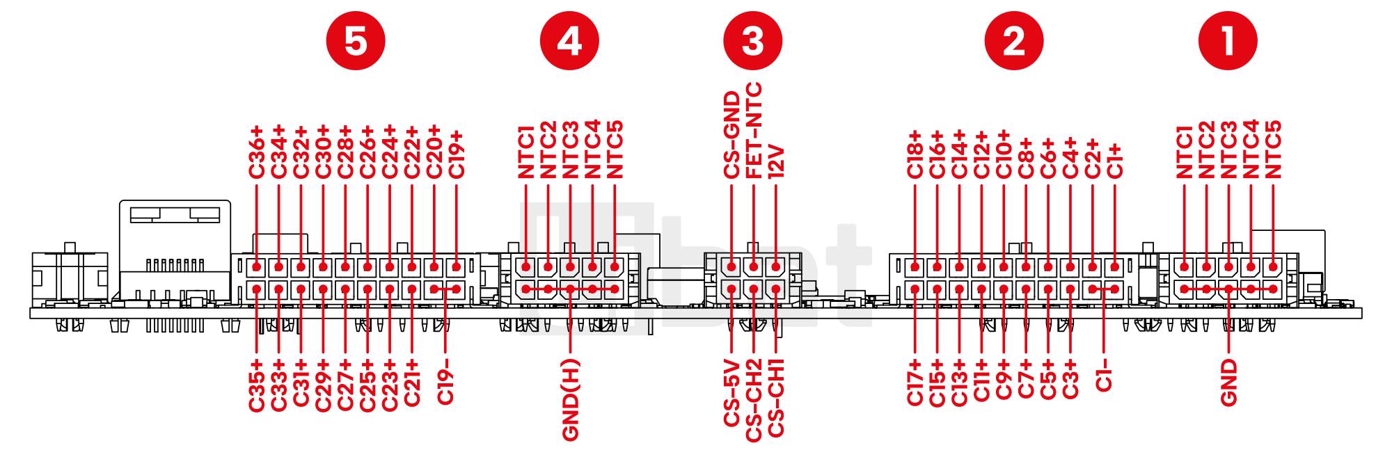
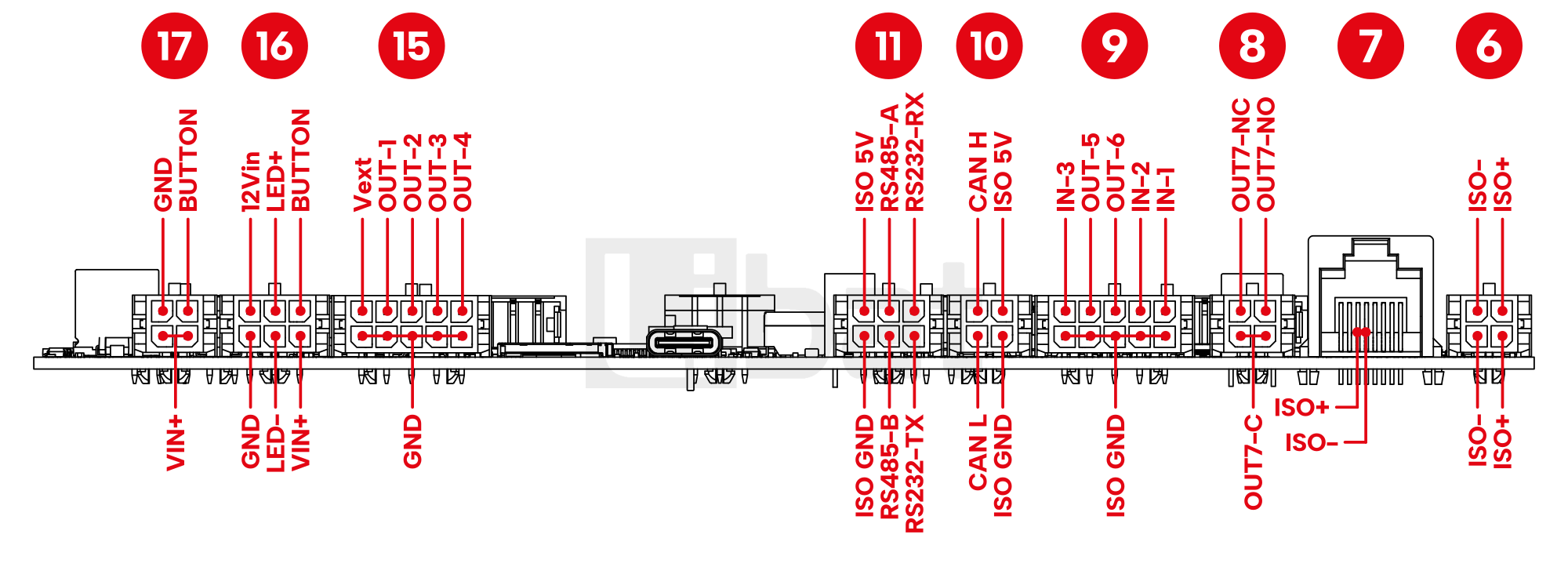
Table.2.1: Connector No#1 Descriptions
| Connector No. | Pin No. | Description (see Fig.2.1 and Fig.2.2) |
|---|---|---|
| 1 | - | Temperature Sensors of Module ID#0 (cells 1 to 18) |
| 1 | 1, 2, 3, 4, 5 | Ground (GND) of the temperature sensors |
| 1 | 6 | External Temperature Sensor No.5 (NTC5) |
| 1 | 7 | External Temperature Sensor No.4 (NTC4) |
| 1 | 8 | External Temperature Sensor No.3 (NTC3) |
| 1 | 9 | External Temperature Sensor No.2 (NTC2) |
| 1 | 10 | External Temperature Sensor No.1 (NTC1) |
Table.2.2: Connector No#2 Descriptions
| Connector No. | Pin No. | Description (see Fig.2.1 and Fig.2.2) |
|---|---|---|
| 2 | - | Cells 1 to 18, Module ID#0 |
| 2 | 1, 2 | Bottom of the battery string, 1st cell's negative tab (C1-) |
| 2 | 3 | 3rd cell's positive tab (C3+) |
| 2 | 4 | 5th cell's positive tab (C5+) |
| 2 | 5 | 7th cell's positive tab (C7+) |
| 2 | 6 | 9th cell's positive tab (C9+) |
| 2 | 7 | 11th cell's positive tab (C11+) |
| 2 | 8 | 13th cell's positive tab (C13+) |
| 2 | 9 | 15th cell's positive tab (C15+) |
| 2 | 10 | 17th cell's positive tab (C17+) |
| 2 | 11 | 1st cell's positive tab (C1+) |
| 2 | 12 | 2nd cell's positive tab (C2+) |
| 2 | 13 | 4th cell's positive tab (C4+) |
| 2 | 14 | 6th cell's positive tab (C6+) |
| 2 | 15 | 8th cell's positive tab (C8+) |
| 2 | 16 | 10th cell's positive tab (C10+) |
| 2 | 17 | 12th cell's positive tab (C12+) |
| 2 | 18 | 14th cell's positive tab (C14+) |
| 2 | 19 | 16th cell's positive tab (C16+) |
| 2 | 20 | 18th cell's positive tab (C18+), the top of Module ID#0 |
Table.2.3: Connector No#3 Descriptions
| Connector No. | Pin No. | Description (see Fig.2.1 and Fig.2.2) |
|---|---|---|
| 3 | - | Current Sensor Connector |
| 3 | 1 | Current Sensor CH1 Sense Input |
| 3 | 2 | Current Sensor CH2 Sense Input |
| 3 | 3 | 5V Output for Current Sensor Power |
| 3 | 4 | 12V Output |
| 3 | 5 | FET Temperature Sensor Input (NTC), not used by the current firmware |
| 3 | 6 | GND for Current Sensor Power |
Table.2.4: Connector No#4 Descriptions
| Connector No. | Pin No. | Description (see Fig.2.1 and Fig.2.2) |
|---|---|---|
| 4 | - | Temperature Sensors of Module ID#1 (cells 19 to 36), GND at the potential of C19- |
| 4 | 1, 2, 3, 4, 5 | Ground of the temperature sensors, at the potential of C19- (C18+) |
| 4 | 6 | External Temperature Sensor No.5 of Module ID#1 (NTC5) |
| 4 | 7 | External Temperature Sensor No.4 of Module ID#1 (NTC4) |
| 4 | 8 | External Temperature Sensor No.3 of Module ID#1 (NTC3) |
| 4 | 9 | External Temperature Sensor No.2 of Module ID#1 (NTC2) |
| 4 | 10 | External Temperature Sensor No.1 of Module ID#1 (NTC1) |
Table.2.5: Connector No#5 Descriptions
| Connector No. | Pin No. | Description (see Fig.2.1 and Fig.2.2) |
|---|---|---|
| 5 | - | Cells 19 to 36, Module ID#1 |
| 5 | 1, 2 | Bottom of Module ID#1 (C19-), on its own wire from the top of Module ID#0 (C18+ in a 36S pack) |
| 5 | 3 | 21st cell's positive tab (C21+) |
| 5 | 4 | 23rd cell's positive tab (C23+) |
| 5 | 5 | 25th cell's positive tab (C25+) |
| 5 | 6 | 27th cell's positive tab (C27+) |
| 5 | 7 | 29th cell's positive tab (C29+) |
| 5 | 8 | 31st cell's positive tab (C31+) |
| 5 | 9 | 33rd cell's positive tab (C33+) |
| 5 | 10 | 35th cell's positive tab (C35+) |
| 5 | 11 | 19th cell's positive tab (C19+) |
| 5 | 12 | 20th cell's positive tab (C20+) |
| 5 | 13 | 22nd cell's positive tab (C22+) |
| 5 | 14 | 24th cell's positive tab (C24+) |
| 5 | 15 | 26th cell's positive tab (C26+) |
| 5 | 16 | 28th cell's positive tab (C28+) |
| 5 | 17 | 30th cell's positive tab (C30+) |
| 5 | 18 | 32nd cell's positive tab (C32+) |
| 5 | 19 | 34th cell's positive tab (C34+) |
| 5 | 20 | 36th cell's positive tab (C36+), the top of Module ID#1 |
Table.2.6: Connector No#6, #7 Descriptions
| Connector No. | Pin No. | Description (see Fig.2.1 and Fig.2.3) |
|---|---|---|
| 6 | - | Isolated Daisy-Chain Connector (4-pin), the same lines as connector 7 |
| 6 | 1 | Isolated daisy-chain communication port (ISO+) |
| 6 | 2 | Isolated daisy-chain communication port (ISO-) |
| 6 | 3 | Isolated daisy-chain communication port (ISO+) |
| 6 | 4 | Isolated daisy-chain communication port (ISO-) |
| 7 | - | Isolated Daisy-Chain Connector (Standard RJ45) |
| 7 | 1, 2, 3, 4, 7, 8 | Not Connected |
| 7 | 5 | Isolated daisy-chain communication port (ISO-) |
| 7 | 6 | Isolated daisy-chain communication port (ISO+) |
Table.2.7: Connector No#8 Descriptions
| Connector No. | Pin No. | Description (see Fig.2.1 and Fig.2.3) |
|---|---|---|
| 8 | 1, 2 | Relay Common Pin (LiMon OUT 7) |
| 8 | 3 | Relay Normally Open Pin (LiMon OUT 7) |
| 8 | 4 | Relay Normally Closed Pin (LiMon OUT 7) |
Table.2.8: Connector No#9 Descriptions
| Connector No. | Pin No. | Description (see Fig.2.1 and Fig.2.3) |
|---|---|---|
| 9 | 1, 2, 3, 4, 5 | ISO GND |
| 9 | 6 | Isolated Input 1 (LiMon INPUT 1) |
| 9 | 7 | Isolated Input 2 (LiMon INPUT 2) |
| 9 | 8 | Isolated Output 2 (LiMon OUT 6) |
| 9 | 9 | Isolated Output 1 (LiMon OUT 5) |
| 9 | 10 | Isolated Input 3 (LiMon INPUT 3) |
Table.2.9: Connector No#10 Descriptions
| Connector No. | Pin No. | Description (see Fig.2.1 and Fig.2.3) |
|---|---|---|
| 10 | 1 | ISO- GND |
| 10 | 2 | CAN 2.0b CH1 Low Pin (CAN L) |
| 10 | 3 | ISO-5V Output |
| 10 | 4 | CAN 2.0b CH1 High Pin (CAN H) |
Table.2.10: Connector No#11 Descriptions
| Connector No. | Pin No. | Description (see Fig.2.1 and Fig.2.3) |
|---|---|---|
| 11 | 1 | RS232 No.0 Transmit Data (Service Port) |
| 11 | 2 | RS485 B Pin |
| 11 | 3 | ISO- GND |
| 11 | 4 | RS232 No.0 Receive Data (Service Port) |
| 11 | 5 | RS485 A Pin |
| 11 | 6 | ISO-5V Output |
Table.2.11: Connector No#12 Descriptions
| Connector No. | Pin No. | Description (see Fig.2.1) |
|---|---|---|
| 12 | - | Port for LiBat Extension Board |
Table.2.12: Connector No#15 Descriptions
| Connector No. | Pin No. | Description (see Fig.2.1 and Fig.2.3) |
|---|---|---|
| 15 | - | High-Side Switch Outputs, for mini relays, not for contactor coils |
| 15 | 1, 2, 3, 4, 5 | GND |
| 15 | 6 | High-Side Switch Output (LiMon OUT 4) |
| 15 | 7 | High-Side Switch Output (LiMon OUT 3) |
| 15 | 8 | High-Side Switch Output (LiMon OUT 2) |
| 15 | 9 | High-Side Switch Output (LiMon OUT 1) |
| 15 | 10 | External Supply Input of the High-Side Switches (Vext) |
Table.2.13: Connector No#16 Descriptions
| Connector No. | Pin No. | Description (see Fig.2.1 and Fig.2.3) |
|---|---|---|
| 16 | 1 | Board VIN+ Output |
| 16 | 2 | External LED- Output (LED GND) |
| 16 | 3 | Board GND |
| 16 | 4 | External Button Input, a push-button to VIN+ (pin 1) starts the BMS |
| 16 | 5 | External LED+ Output |
| 16 | 6 | +12V Supply Input (12Vin), never together with VIN+ on connector 17 |
Table.2.14: Connector No#17 Descriptions
| Connector No. | Pin No. | Description (see Fig.2.1 and Fig.2.3) |
|---|---|---|
| 17 | 1, 2 | Board VIN+ (Board Main Power) |
| 17 | 3 | External Button Input, a push-button to VIN+ (pin 2) starts the BMS |
| 17 | 4 | Board GND (Board Main Power) |
Table.2.15: SW1 Descriptions
| Part | Lever | Description (see Fig.2.1) |
|---|---|---|
| SW1 | - | CAN and RS485 Termination Switch: ON puts 120 Ω across the line, only at the two ends of a line |
| SW1 | 1 | Lever 1: RS485 termination, 120 Ω between RS485 A and B (connector 11 pins 5 and 2), the same as lever 2 |
| SW1 | 2 | Lever 2: RS485 termination, the same as lever 1 |
| SW1 | 3 | Lever 3: CAN termination, 120 Ω between CAN H and CAN L (connector 10 pins 4 and 2), the same as lever 4 |
| SW1 | 4 | Lever 4: CAN termination, the same as lever 3 |