3. INT101 Connection
The INT101 needs three things: the extension port of the BMS for power and data, a GSM antenna and a nanoSIM card. The GNSS module works with its own antenna; an external one is optional.
3.1 Block Diagram
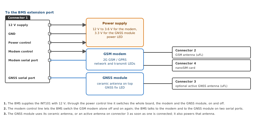
The BMS supplies the INT101 with 12 V through connector 1 and talks to the modem and to the GNSS module on two serial ports. Two control lines let the BMS switch the whole board on and off and switch the modem alone off and on again.
Fig.3.1.1: INT101 Block Diagram
3.2 Mounting on the BMS
The INT101 stacks on the BMS: the 2 x 6 socket on its bottom side (connector 1) plugs onto the pin header of the BMS extension port, pin 1 on pin 1, and snap-in spacers in the holes H1 to H4 (5. Mechanical) hold the board, one wherever the BMS has a hole under the INT101 hole: four on the BMS1810, three on the BMS1820, BMS3610, BMS1601 and BCU2002; no screws are needed. The extension port is not fitted on a standard BMS; it is fitted at the factory when the BMS is ordered with an INT101.
Table.3.2.1: Extension Port of the BMS Boards
| BMS | Extension Port |
|---|---|
| BMS1820 | Connector 9 |
| BMS3610 | Connector 12 |
| BCU2002 | Connector 14 |
| BMS1810 | Connector 15 |
| BMS1601 | Connector 14 |
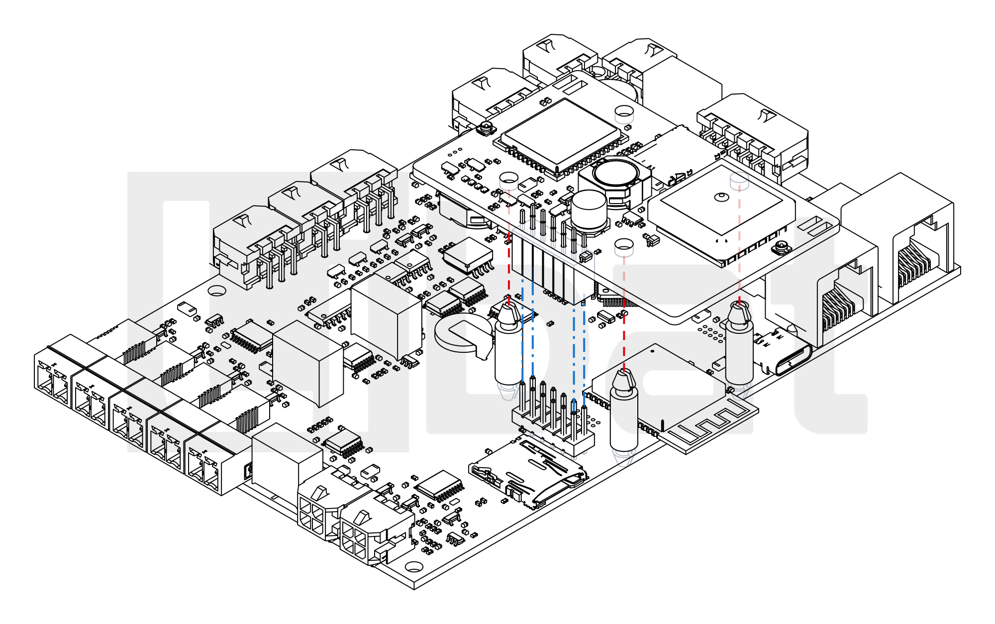
The figures below show it on a BMS1810, drawn from the STEP files of both boards: the four 3.2 mm holes around connector 15 of the BMS1810 have the same pattern as the holes H1 to H4 of the INT101, so the snap-in spacers line the socket of the INT101 up with the pin header of the BMS1810 by themselves. Fit the INT101 in this order; on the other boards use the extension port of Table.3.2.1 and three spacers (Fig.3.2.2 to Fig.3.2.5):
- Unplug every cell connector and the supply connector of the BMS, and the GSM antenna cable if one is fitted.
- Press the snap-in spacers into the 3.2 mm holes around the extension port (connector 15 on the BMS1810) until they click.
- Set the INT101 over them, its socket over the pin header of the extension port and its holes over the spacer heads.
- Press the INT101 down evenly, near the socket and near each spacer, until the pin header sits fully in the socket and every spacer clicks into its hole.
- Connect the GSM antenna to connector 2, insert the SIM card (3.3) and switch the BMS on.
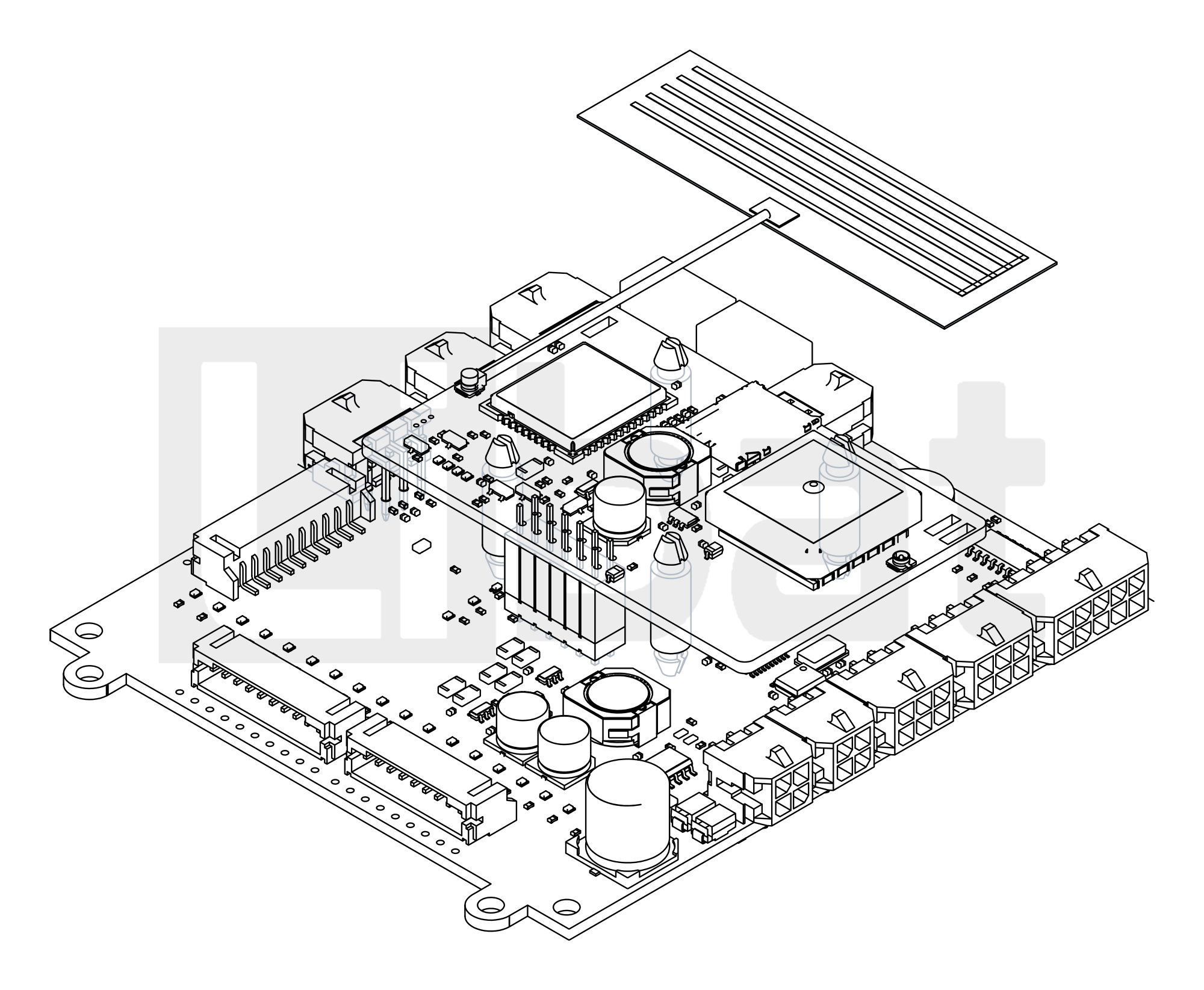
Fig.3.2.1: INT101 on a BMS1810, Exploded and Mounted
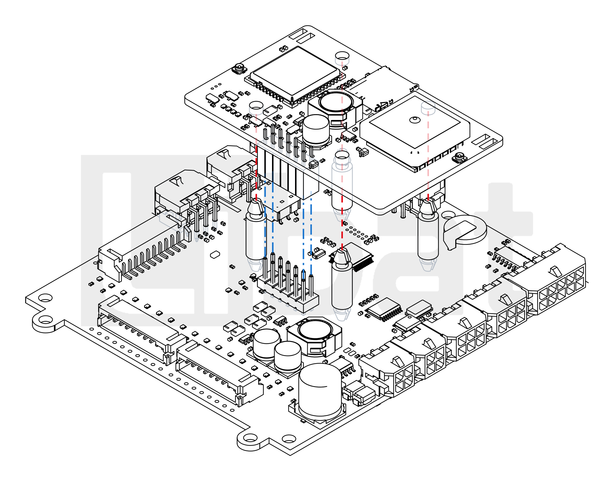
Red: spacer to hole · Blue: pin header of the BMS1810 to the socket of the INT101 · Light grey: parts hidden by the INT101
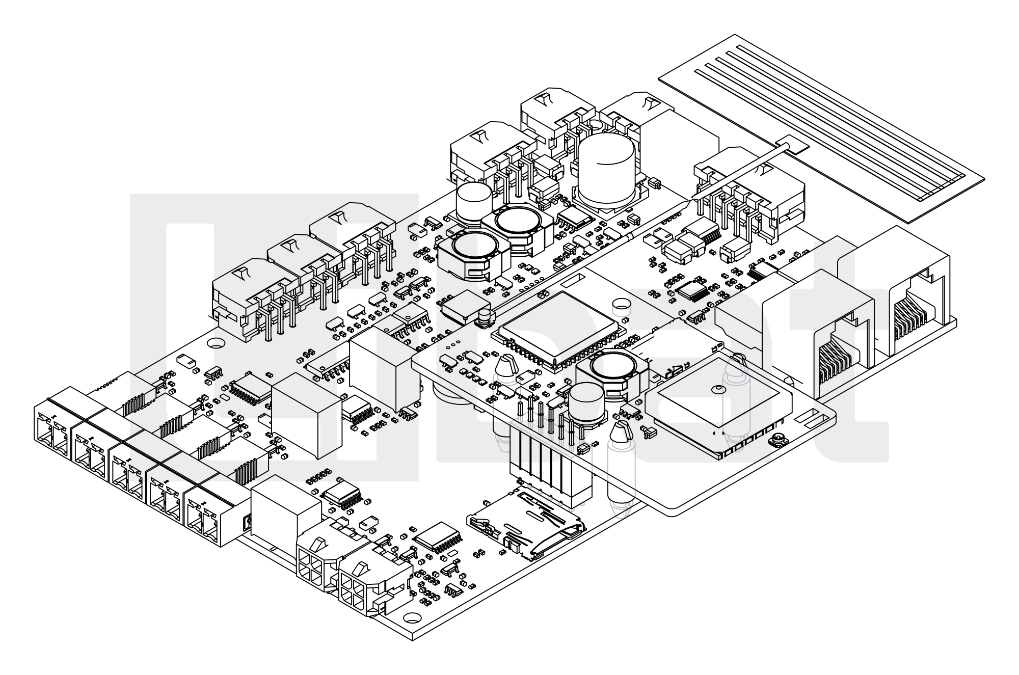
On the BMS1820, the BMS3610, the BMS1601 and the BCU2002 the INT101 sits the same way on the pin header of the extension port, turned with it, and on three snap-in spacers: these boards have no hole under the fourth INT101 hole. On the BMS1601 the INT101 reaches past the board edge.
Fig.3.2.2: INT101 on a BMS1820, Exploded and Mounted
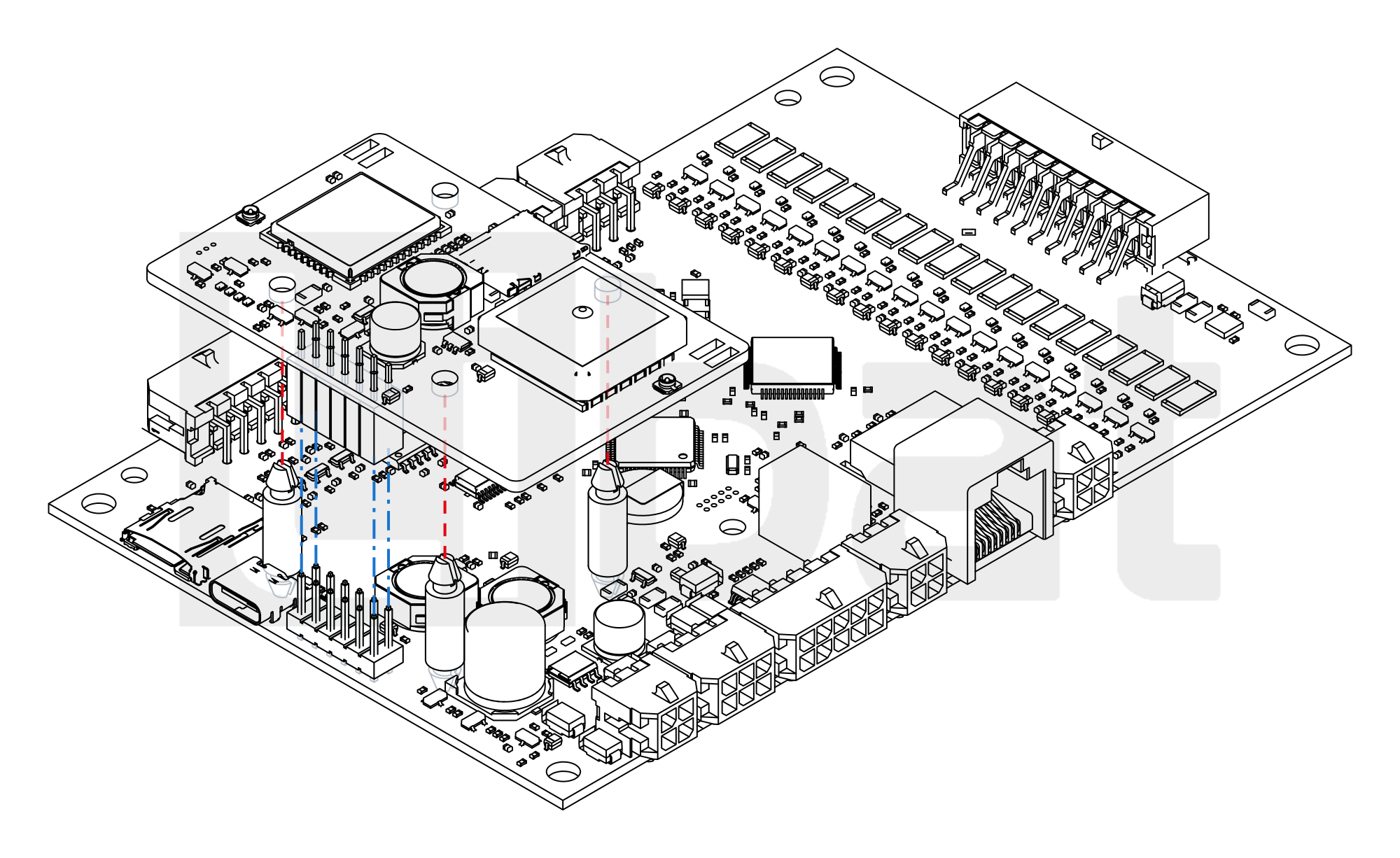
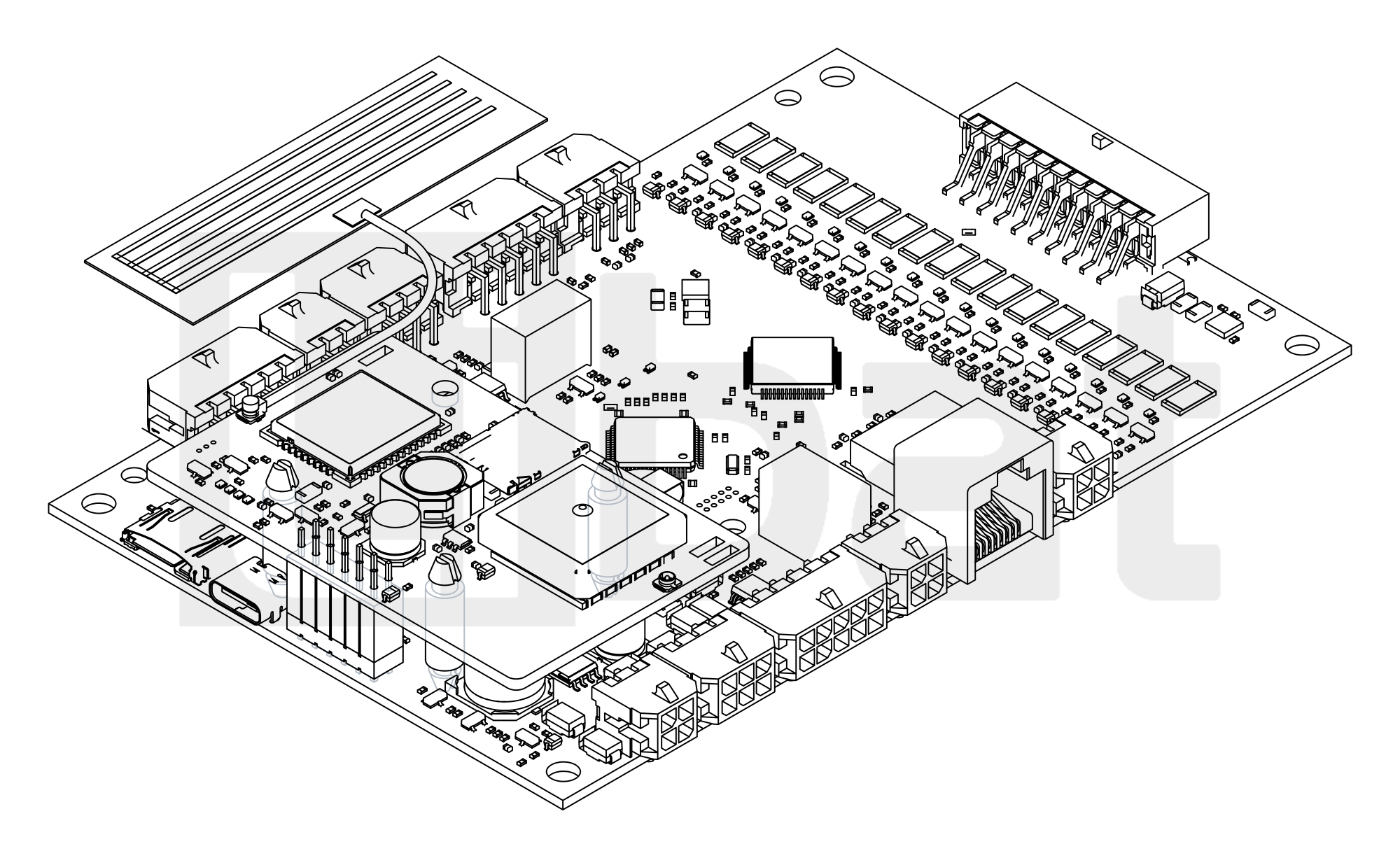
Fig.3.2.3: INT101 on a BMS3610, Exploded and Mounted
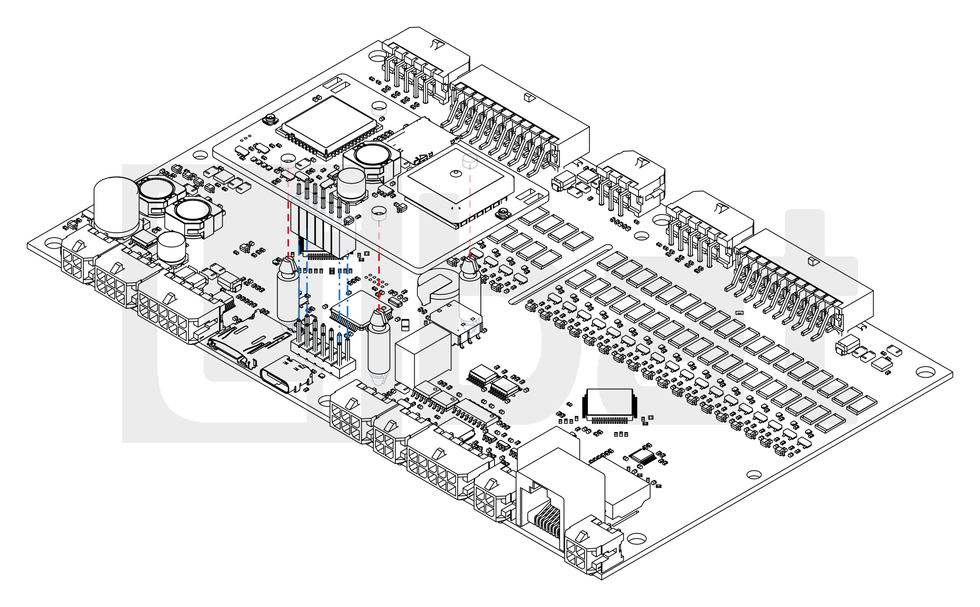
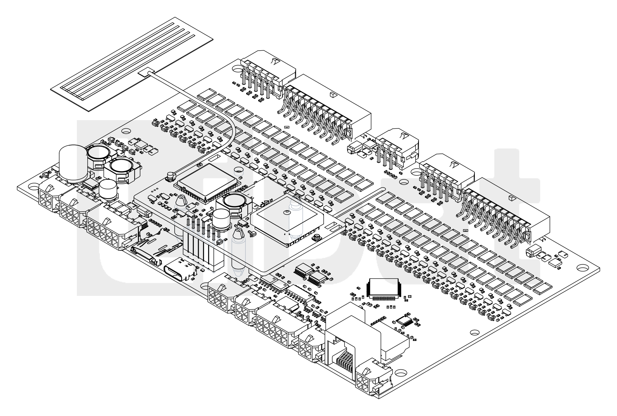
Fig.3.2.4: INT101 on a BMS1601, Exploded and Mounted
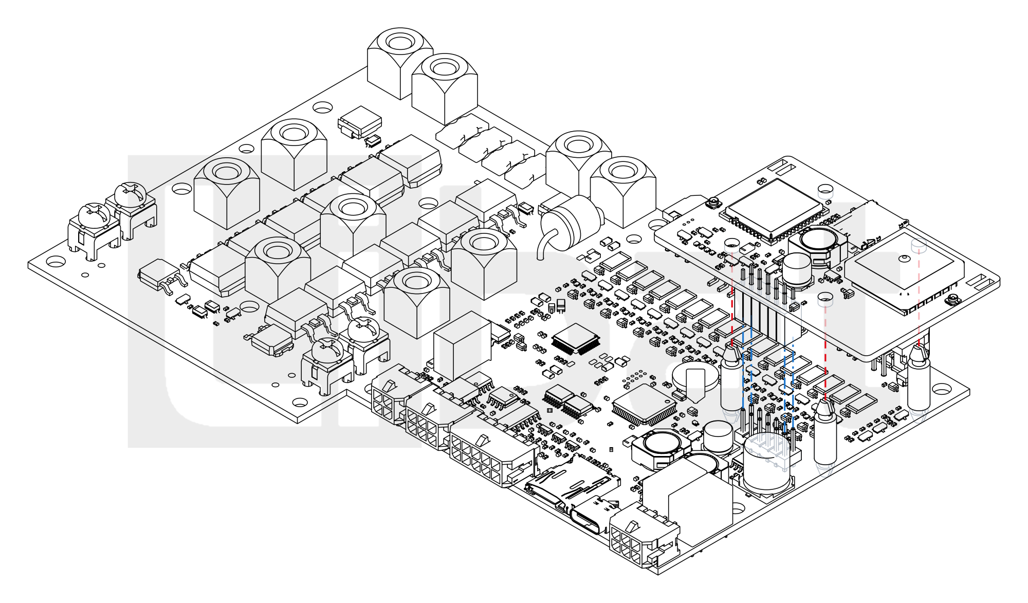
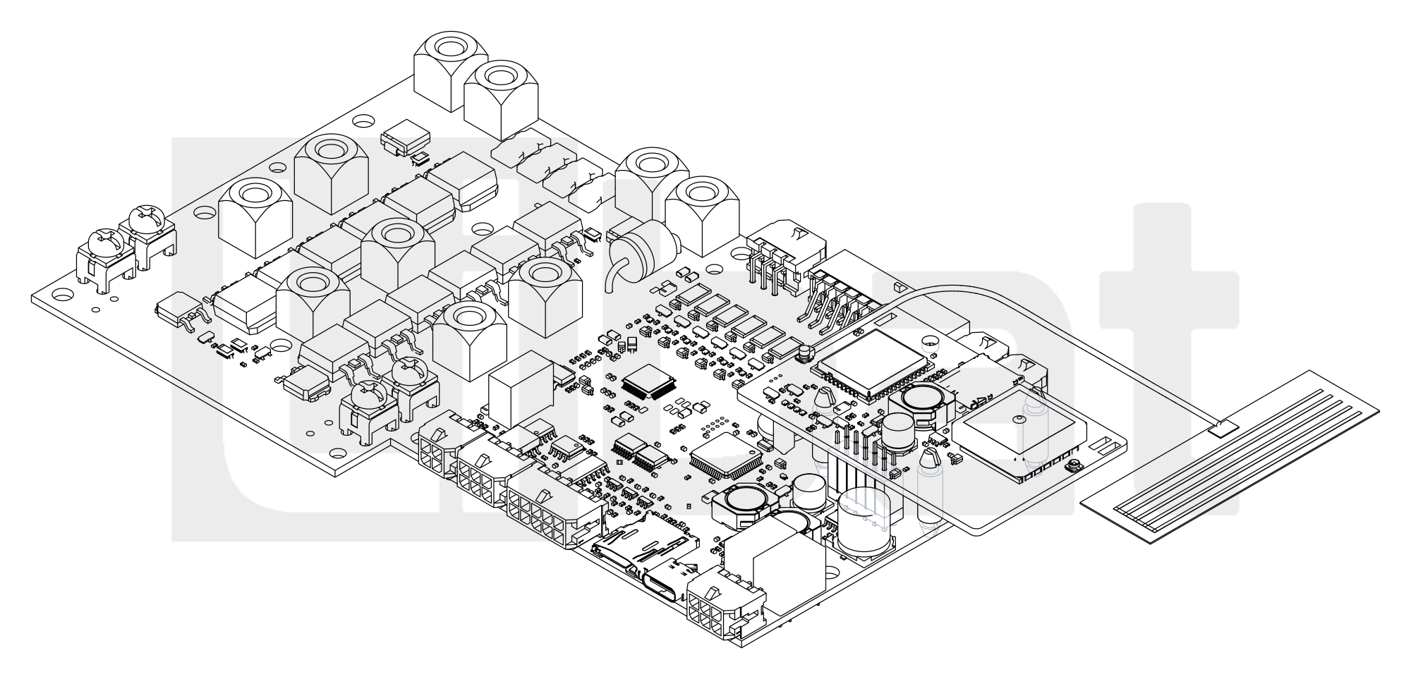
Fig.3.2.5: INT101 on a BCU2002, Exploded and Mounted
Warning
Fit or remove the INT101 only after every cell connector and the supply connector of the BMS are unplugged; switching the BMS off is not enough, because a slip while the cells are still connected can damage both boards. Check before you press it down that every pin of the header sits under the socket: a socket that is off by one row connects the wrong pins.
3.3 GSM Antenna and SIM Card
The INT101 comes with a flat GSM antenna on a thin cable that ends in a uFL plug (Fig.3.2.1 b). The cable is held in a small notch at the edge of the INT101; it leaves the board there and bends gently towards the antenna, never sharply. Set the plug straight over connector 2 and press it down until it clicks; to take it off, lift it straight up, never by the cable. Stick the antenna flat on a plastic part of the enclosure, outside any metal and away from power cables; a battery in a metal case needs an antenna on the outside of the case, with a cable through the wall.
Keep the antenna away from the analog wiring
The GSM antenna sends short radio bursts that can disturb the analog measurements of the BMS. Place the antenna and its cable away from the cell voltage wires, the NTC wires and the current sensor cable, and do not run the antenna cable along them.
The INT101 takes a nanoSIM card with a data plan that works on a 2G (GSM/GPRS) network; check that a 2G network is available where the battery will be used. The holder (4) is a push-push type: one push locks the card, the next push releases it. Switch the BMS off before you insert or remove the card.
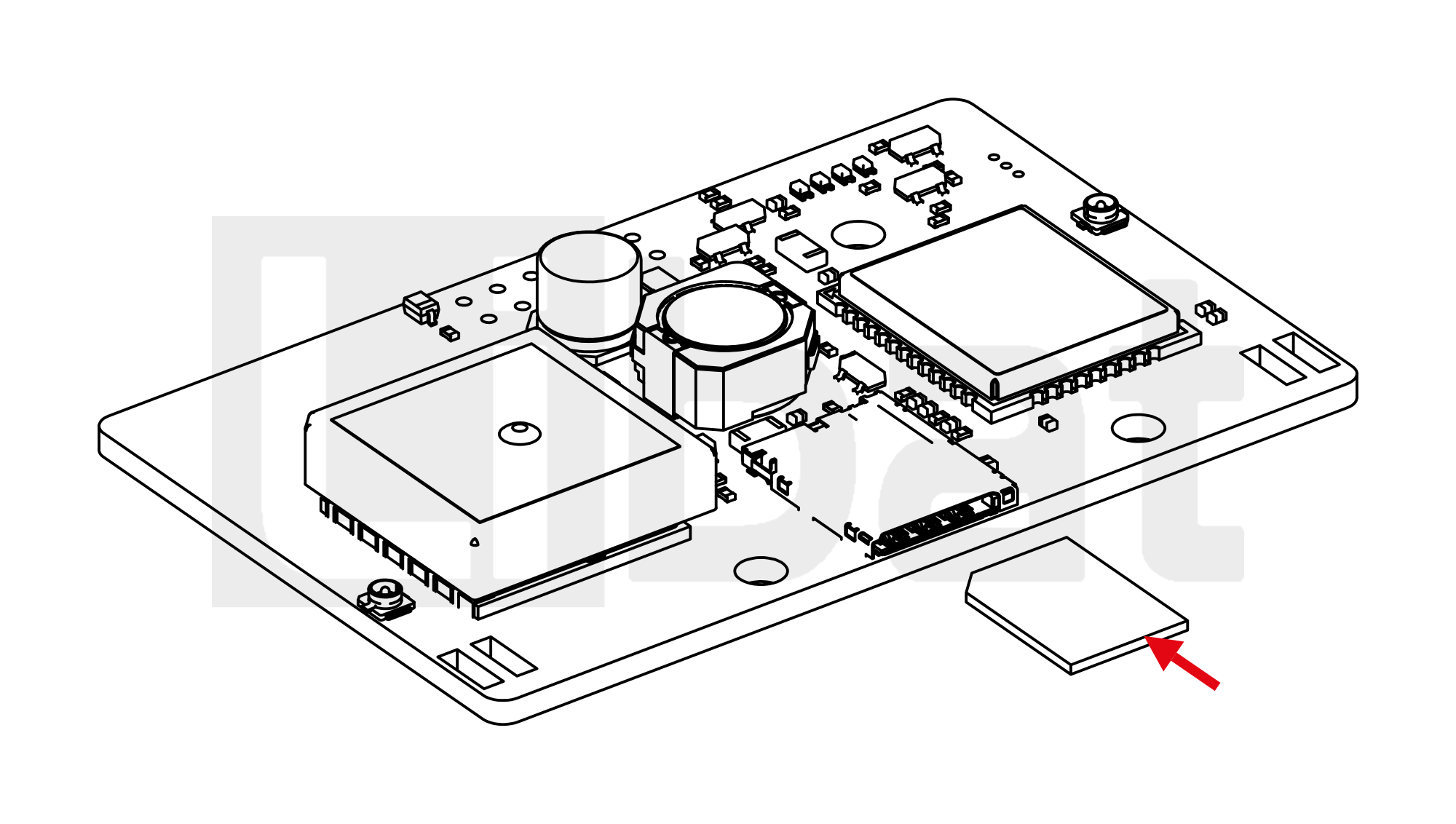
To insert the card (Fig.3.3.1 a):
- Hold the card with its contacts down, towards the board, and its cut corner first, as in the figure.
- Slide it straight into the slot of the holder at the board edge.
- Push it in with a fingertip until it clicks; the card stays in, flush with the holder.
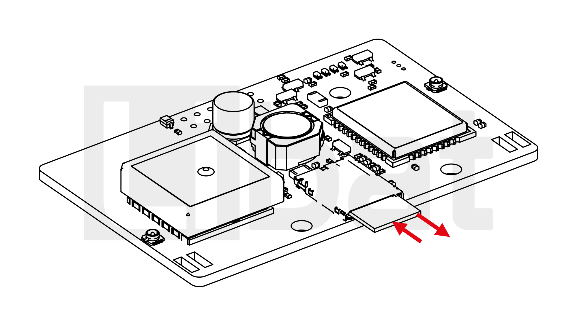
To remove the card (Fig.3.3.1 b):
- Push the card in once more until it clicks.
- Let go: the spring pushes the card half out of the slot.
- Pull it straight out.
Fig.3.3.1: nanoSIM Card in Holder 4
3.4 GNSS Antenna
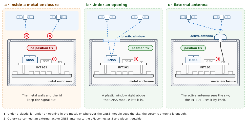
The GNSS module (6) works with its ceramic antenna on top, which needs a view of the sky. Metal surfaces and closed spaces weaken or block the GNSS signal, so inside a metal enclosure, or under a metal lid, the module may find no position at all. If the metal has a small opening, for example a plastic window, place the INT101 so that the GNSS module sits right under it. Otherwise connect an external active GNSS antenna for 3.3 V to the uFL connector 3 and place it outside, where it sees the sky more freely; the INT101 powers the antenna and switches to it as soon as it is connected. Without an external antenna the ceramic antenna is used.
Fig.3.4.1: GNSS Antenna Inside, Under an Opening and Outside
3.5 Cloud Connection
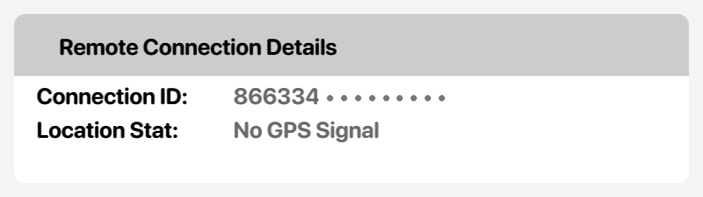
The BMS firmware runs the modem and the GNSS module and sends the battery data to the LiBat™ cloud over a secure connection; LiBat™ sets the cloud connection up for each BMS. LiMon™ shows the connection ID and the GPS status of the BMS (4.3 In LiMon™).
Fig.3.5.1: Remote Connection Details in LiMon™