2. DIS110 Pinouts and Descriptions
DIS110 carries the LED bar, four status LEDs and two buttons on its front (1 to 7), and the connector to the BMS and the DIP switch on its back (8 and 9). The numbers below are used on every page of the DIS110.
Warning
Connect the DIS110 to the BMS only while the BMS is off, and check every pin of connector 8 against the BMS connector before you plug it in.
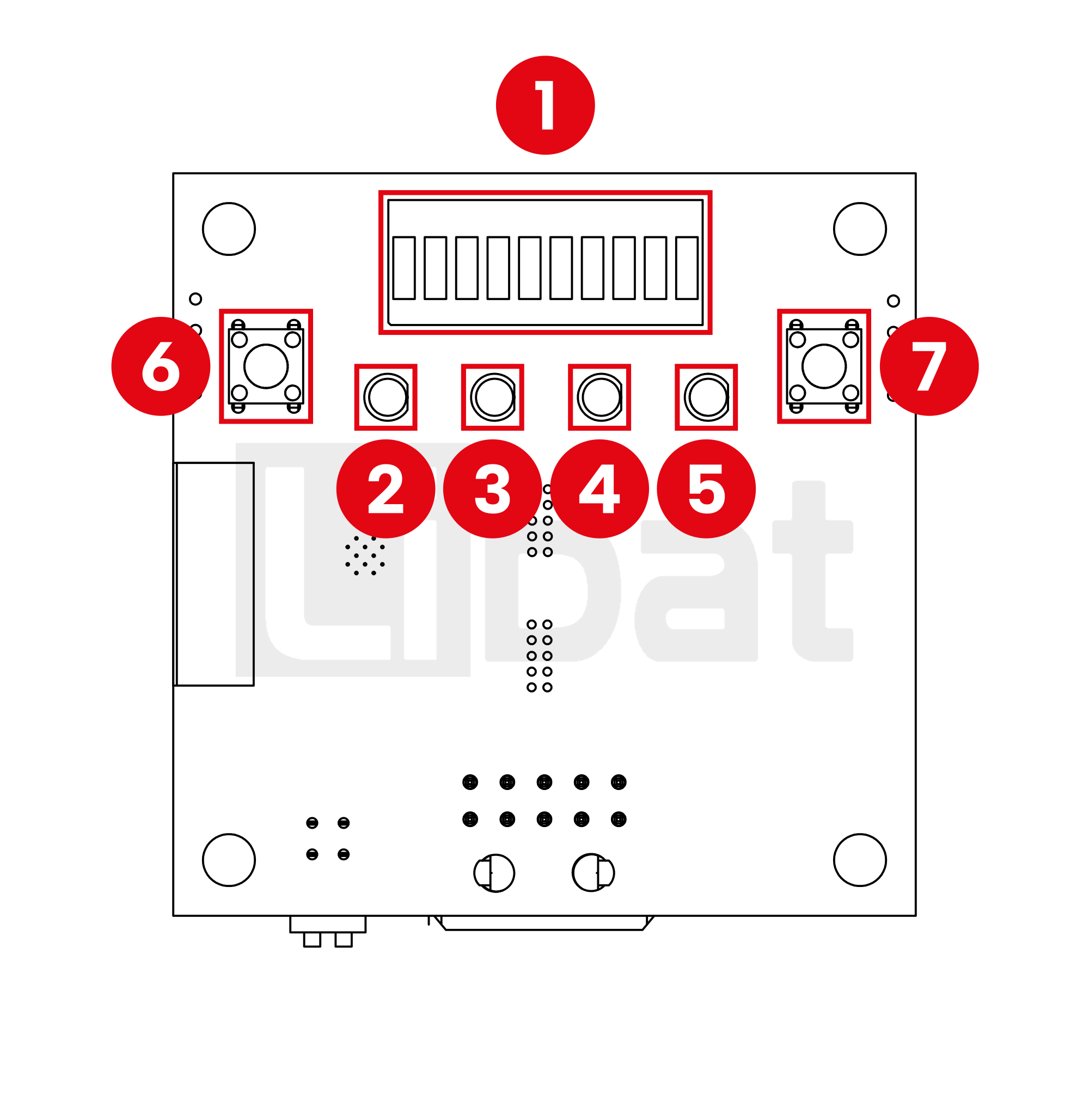
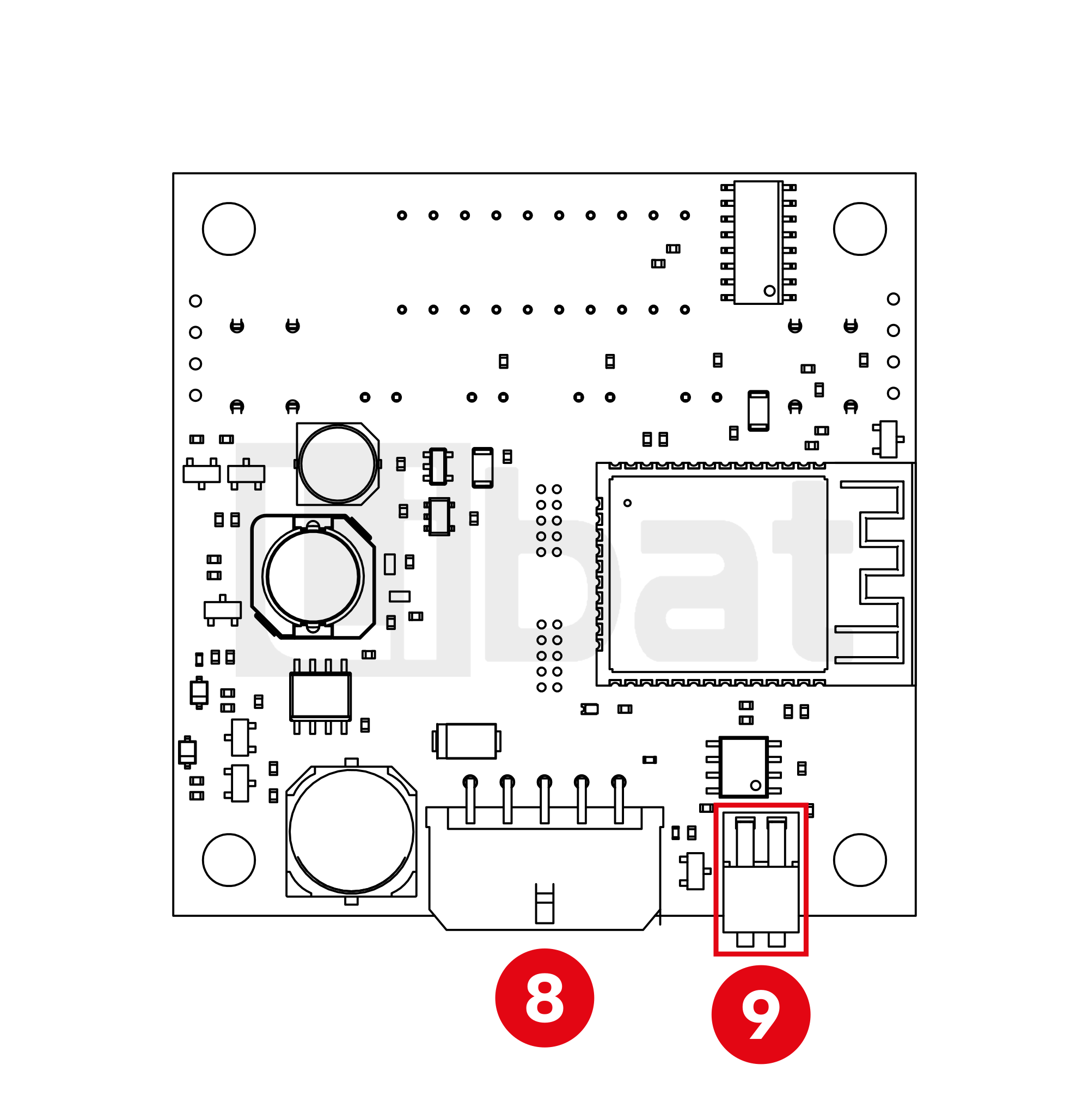
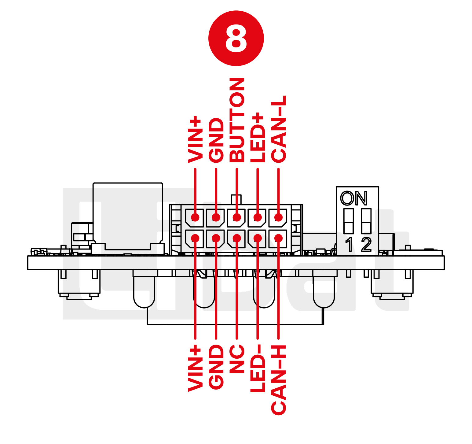
Table.2.1: Connector No#1, #2, #3, #4, #5, #6, #7 Descriptions
| Connector No. | Pin No. | Description (see Fig.2.1) |
|---|---|---|
| 1 | - | LED bar, 10 segments from red to blue: the state of charge, about 10 % per segment |
| 2 | - | LED 1, Wi-Fi: off = Wi-Fi off, on = Wi-Fi active, blinking = a device is connected or a Wi-Fi network joined |
| 3 | - | LED 2, BLE: off = BLE off, on = advertising, blinking = an app is connected |
| 4 | - | LED 3, CAN: blinking while the battery status arrives, off when none came for 3 s |
| 5 | - | LED 4, BMS STAT: driven by the BMS through connector 8 (pins 2 and 7) |
| 6 | - | Display button: wakes Wi-Fi; held for 5 s it opens the device menu |
| 7 | - | BMS button: connects VIN+ to pin 8 of connector 8, which starts the BMS and the DIS110; on a separate supply it turns on the DIS110 only |
Table.2.2: Connector No#8 Descriptions
| Connector No. | Pin No. | Description (see Fig.2.2 and Fig.2.3) |
|---|---|---|
| 8 | 1 | CAN H, to CAN H of the BMS |
| 8 | 2 | BMS STAT LED cathode, to the LED- output of the BMS |
| 8 | 3 | Not connected |
| 8 | 4 | GND |
| 8 | 5 | Supply input, from the VIN+ output of the BMS or a separate supply |
| 8 | 6 | CAN L, to CAN L of the BMS |
| 8 | 7 | BMS STAT LED anode, to the LED+ or 12 V output of the BMS |
| 8 | 8 | To the button input of the BMS: the BMS button connects it to VIN+; not connected on a separate supply |
| 8 | 9 | GND |
| 8 | 10 | Supply input, the same as pin 5 |
Table.2.3: Connector No#9 (SW1) Descriptions
| Part | Lever | Description (see Fig.2.2) |
|---|---|---|
| 9 | 1 | Lever 1: CAN termination, 120 Ω between CAN H and CAN L; ON only at the end of the CAN line |
| 9 | 2 | Lever 2: keeps the DIS110 on while it has supply, the shutdown setting does not apply; OFF for normal use |
Danger
Check every connection and cable before you plug a connector into the DIS110 or the BMS.