3. BMS1802 Battery Connection
BMS1802 measures packs of 5 to 18 cells in series. This page shows how to wire the cells, the temperature sensors and the daisy chain to the master, and what to set in LiMon™ afterwards.
3.1 Power Supply and RUN LED
BMS1802 gets its power from its own cells through connector 1; it needs no other supply. It needs at least 11 V from its cells (about 2.2 V per cell on a 5S pack); below that the module does not start and the master reports Slave Module Communication Error.
RUN LED
The RUN LED shows whether the module is awake. It lights for a moment when the cells are connected, stays on while the master talks to the module, and goes off about 2 s after the communication stops, when the module goes to deep sleep. An external RUN LED can go on connector 4; the STAT LED is not used.
3.2 Cell Connection
Warning
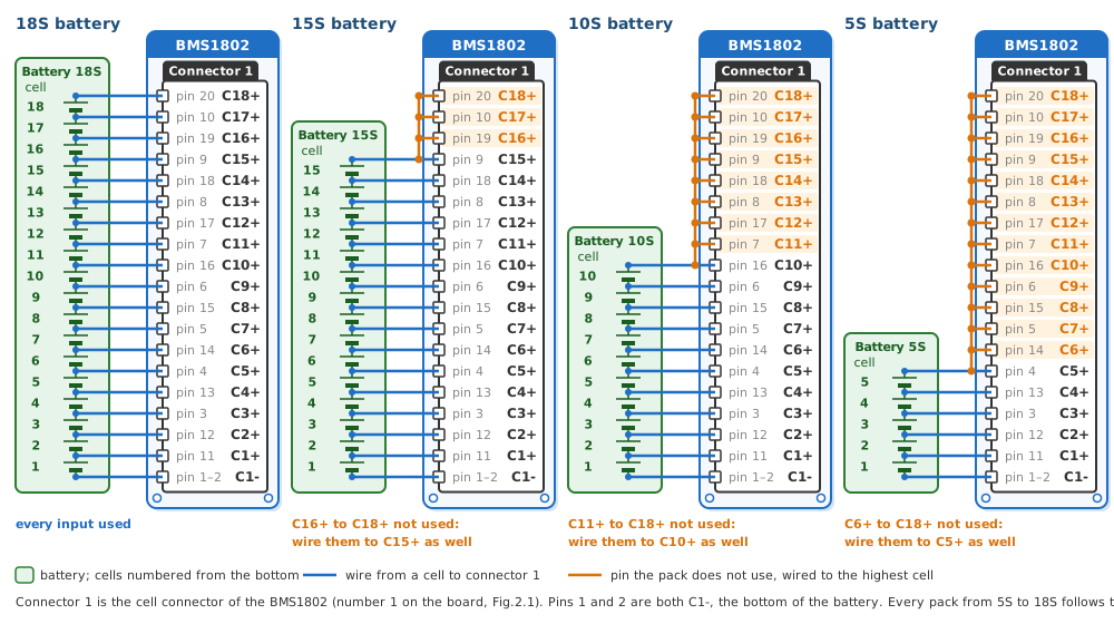
Take C1- and the tap of the top cell on wires of their own, not from the B- and B+ power cables of the pack. A wire shared with the load current drops voltage and gives wrong cell readings.
Info
Tie the unused inputs to the highest cell, on the cell measurement cable or at the connector; open inputs give wrong cell measurements.
Fig.3.2.1: BMS1802 5S to 18S Battery Cell Connections
Tip
After the wiring, check the cell count of the module as 3.5 describes.
3.3 Temperature Sensor Connection
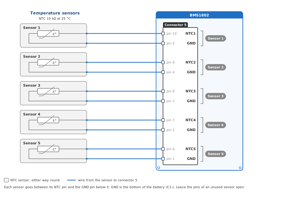
Up to five NTC sensors connect to connector 5, each between its NTC pin and the GND pin below it; in LiMon™ Live View they are **T1** to **T5** of the module. The board measures its own temperature in the balancing area as well: it is the **PCB Temp** of the module, which the PCB and balancing temperature limits watch ([User Manual 3.5 Temperature Limits](../user-manual/configuration/temperature-limits.md)).
Fig.3.3.1: BMS1802 Temperature Sensor Connection
Tip
Leave the pins of an unused sensor open: an input without a sensor is ignored. Check in Live View that every connected sensor reads a value.
3.4 Master Connection via Isolated Daisy Chain Communication Port
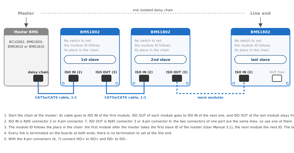
BMS1802 has no firmware of its own: the master commands it over the isolated daisy chain to measure and to balance its cells, and handles every event. Connect the daisy chain as shown below.
Tip
Use CAT5e or CAT6 cable, up to 50 m. The cable from the master or the module before goes to ISO IN (RJ45 connector 2 or 4-pin connector 7), the cable to the next module leaves from ISO OUT (RJ45 connector 3 or 4-pin connector 6); ISO OUT of the last module stays free. Connect ISO+ to ISO+ and ISO- to ISO-, one to one; an RJ45 cable wired 1:1 does this. The module ID follows the place in the chain, and every link is terminated on the boards, so there is nothing to set on the board; see the pinout.
Fig.3.4.1: BMS1802 Isolated Daisy Chain Connection
3.5 Settings in LiMon™ and First Check
After the wiring, set the master in LiMon™ and restart it so that it finds the modules:
- Slave Module Type Selection: BMS1802. All slaves of one master are the same type; BMS1802 and BMS1202 cannot be mixed on one chain.
- Module ID#n: the cell count of every module, in the order of the chain: the first module after the master is the first slave ID of the master. A master takes a limited number of modules: 16 on BCU2002, 14 on BMS1820, 9 on BMS1810 and 8 on BMS3610 (User Manual 3.1 Battery Topology).
- Save, restart the master and check in Live View that every module is there with the cell count you set. The full procedure is in 2.1 Commissioning Checklist.
Table.3.5.1: Wiring Faults and What the Master Reports
| Wiring fault | Event | What to check |
|---|---|---|
| A cell tap missing or loose, an unused input not tied to the highest cell, or a cell count in LiMon™ that does not match | (26) Cell Connection Error | Connected Cells of the module, then its cell connector 1 and the cell count in LiMon™ |
| A daisy chain cable or connector broken, or a module below 11 V | (29) Slave Module Communication Error | Which module is missing in Live View, then its cables and its cell voltages |
| A temperature sensor not connected or its wire broken | none; the input is ignored | That the sensor reads a value in Live View |
After a fault is repaired, restart the master. All events and their causes are in 6.1 Events and What to Do.