3. INT201 Connection
INT201 connects a PC to one serial port at a time: the RS232 service port of a LiBat™ BMS for LiMon™, an RS485 line or a 3.3 V or 5 V UART. This page shows the block diagram of the board, the wiring for each mode, the mode switch and the RS485 termination.
3.1 Block Diagram
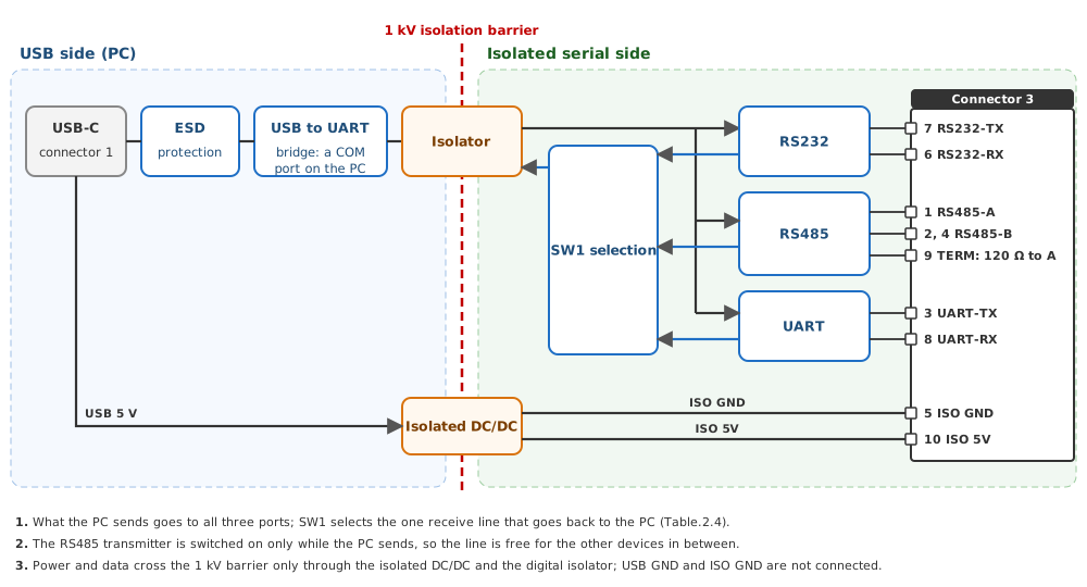
The USB side and the serial side of the INT201 are isolated from each other; power crosses the barrier through an isolated DC/DC converter and the data through a digital isolator. What the PC sends goes to all three ports, and the mode switch selects the port whose receive line goes back to the PC.
Fig.3.1.1: INT201 Block Diagram
3.2 USB and Power
INT201 takes its power from the USB port of the PC; it needs no other supply. Connect it with a USB Type-C cable (connector 1). The PC shows it as a serial port once the driver is installed (1. Introduction). The data LED (connector 2) blinks while data is sent or received.
Info
The serial side is isolated from USB and the PC (1 kV). ISO GND on connector 3 is the ground of the serial ports, not the ground of the PC.
3.3 Mode Switch
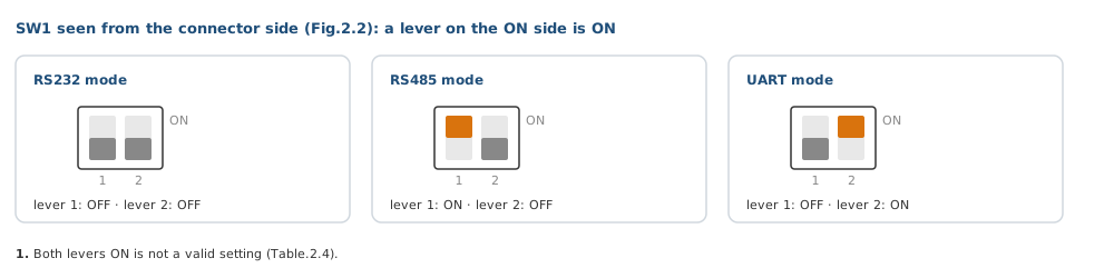
The mode switch SW1 (connector 4) selects the port the INT201 receives from. What the PC sends goes out on all three ports at the same time.
Fig.3.3.1: INT201 Mode Switch Settings
3.4 Port Connection
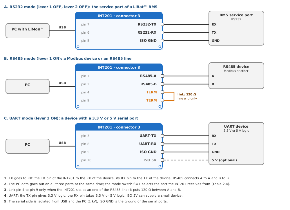
Connect the device to connector 3 for the mode set on SW1. For LiMon™, use RS232 mode and the RS232 service port of the BMS; the pins of the service port are on the pinout page of each board.
Fig.3.4.1: INT201 Connections in RS232, RS485 and UART Mode
RS485 termination
Link pin 4 to pin 9 of connector 3 only when the INT201 is at an end of the RS485 line; it puts 120 Ω between A and B. Leave the pins open in the middle of a line and in RS232 or UART mode.
Danger
Check every connection and cable before you plug connector 3 into the INT201 or the device.