2. DIS700 Pinouts and Descriptions
The DIS700 carries the touchscreen (1) on its front, the status LED (2) and the on/off button (4) on top and the connector to the BMS (3) underneath. The numbers follow the letters A to D of the DIS700 user manual and are used on every page of the DIS700.
Warning
Connect the DIS700 to the BMS only while the BMS is off, and check every pin of the cable connector against Table.2.2 before you plug it in.
Fig.2.1: DIS700-E, Front
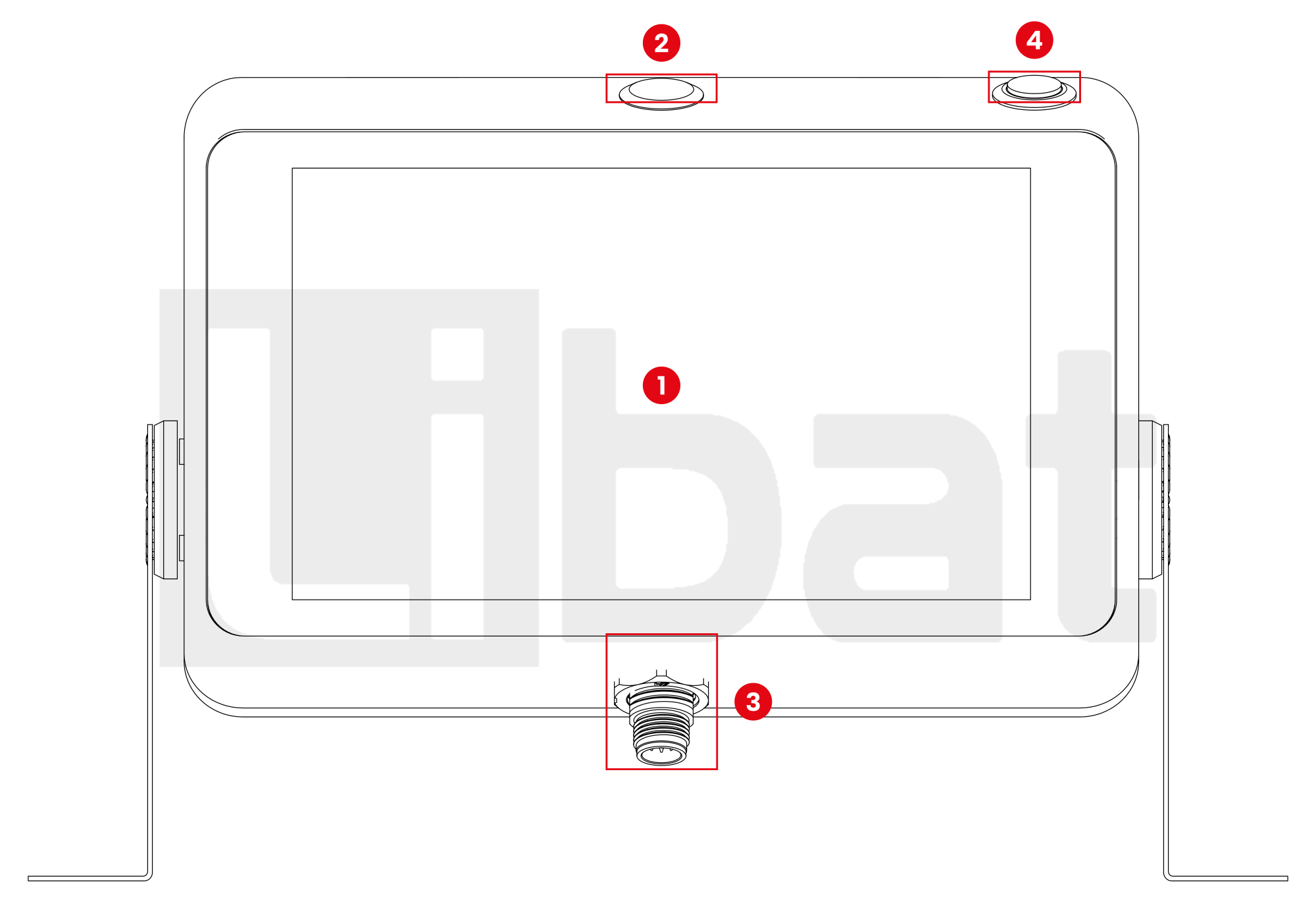
Table.2.1: DIS700 Parts
| No. | Part | Description (see Fig.2.1) |
|---|---|---|
| 1 | Touchscreen | 7-inch touchscreen, 1024 x 600: shows the BMS data; the buttons along its bottom edge open the pages (4. Operation) |
| 2 | Status LED | Green while BMS data arrives and no event tile is red; red when a tile is red or no BMS data arrives |
| 3 | Connector | 8-pin circular connector with pins, underneath the DIS700: supply and CAN to the BMS (Table.2.2) |
| 4 | On/off button | Switches the supply on pin 6 of connector 3, and with it the DIS700, on and off |
Fig.2.2: Connector 3
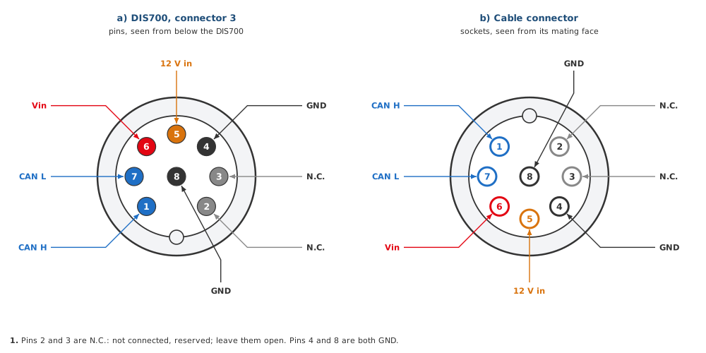
Table.2.2: Connector No#3 Descriptions
| Connector No. | Pin No. | Description (see Fig.2.2) |
|---|---|---|
| 3 | 1 | CAN H, isolated; to CAN H of the BMS |
| 3 | 2 | N.C.: not connected, reserved; leave it open |
| 3 | 3 | N.C.: not connected, reserved; leave it open |
| 3 | 4 | GND |
| 3 | 5 | 12 V supply input, 10.8 V to 13.2 V, for a separate 12 V supply; not switched by the on/off button |
| 3 | 6 | Supply input Vin, 18 V to 80 V, from the VIN+ output of the BMS; switched by the on/off button |
| 3 | 7 | CAN L, isolated; to CAN L of the BMS |
| 3 | 8 | GND, the same as pin 4 |