1. BMS1820 Introduction
LiBat™ BMS1820 is an advanced battery management system master designed for distributed master-slave battery applications in demanding industrial environments. This fully digital device is a ready-to-use solution for 5S-18S master battery management systems: it measures up to 18 cells on the board, drives up to 14 BMS1802 or BMS1202 slave modules over an isolated daisy chain, and talks to the system over galvanically isolated CAN Bus, RS485, RS232 and I/O. Powered from 12V or directly from the battery, it adapts to high voltage, high power and high energy applications through external electrical components such as contactors and current sensors. With four automotive-grade high-side switches for mini relays and a relay output, the BMS1820 delivers flexible control and, once configured with the correct system parameters, operates seamlessly without the need for ongoing user interaction.
Key Features:
- Built in 5S - 18S cell measurement with 0.1mV resolution
- Up to 420mA adjustable passive balancing current
- Wide input supply range (12V - 80V), 12V or battery powered
- Isolated 1 x CANBus 2.0b, 1 x RS232, 1 x RS485 communication
- Cloud connection and OTA firmware updates with an optional extension board (connector 9)
- Advanced I/O: 3 isolated logic inputs, 2 isolated logic outputs, 4 automotive high-side switches, 1 relay output
- Dual channel external current measurement
- Up to 5 external NTC temperature probes, 1 on-board NTC
- Standalone, Master and Multi-Master operating modes
- Up to 14 slave modules (BMS1802 / BMS1202) via isolated daisy-chain
- Expandable up to 270 cells total with slave module connection
- Low power consumption when shut down
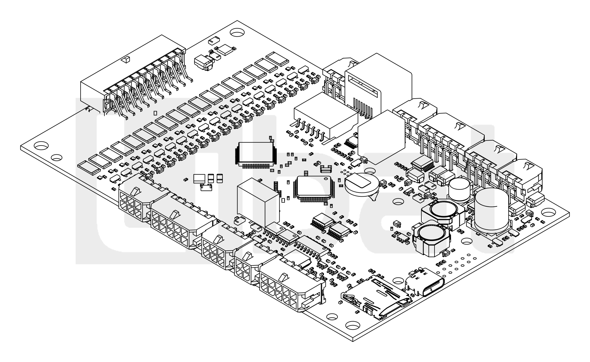
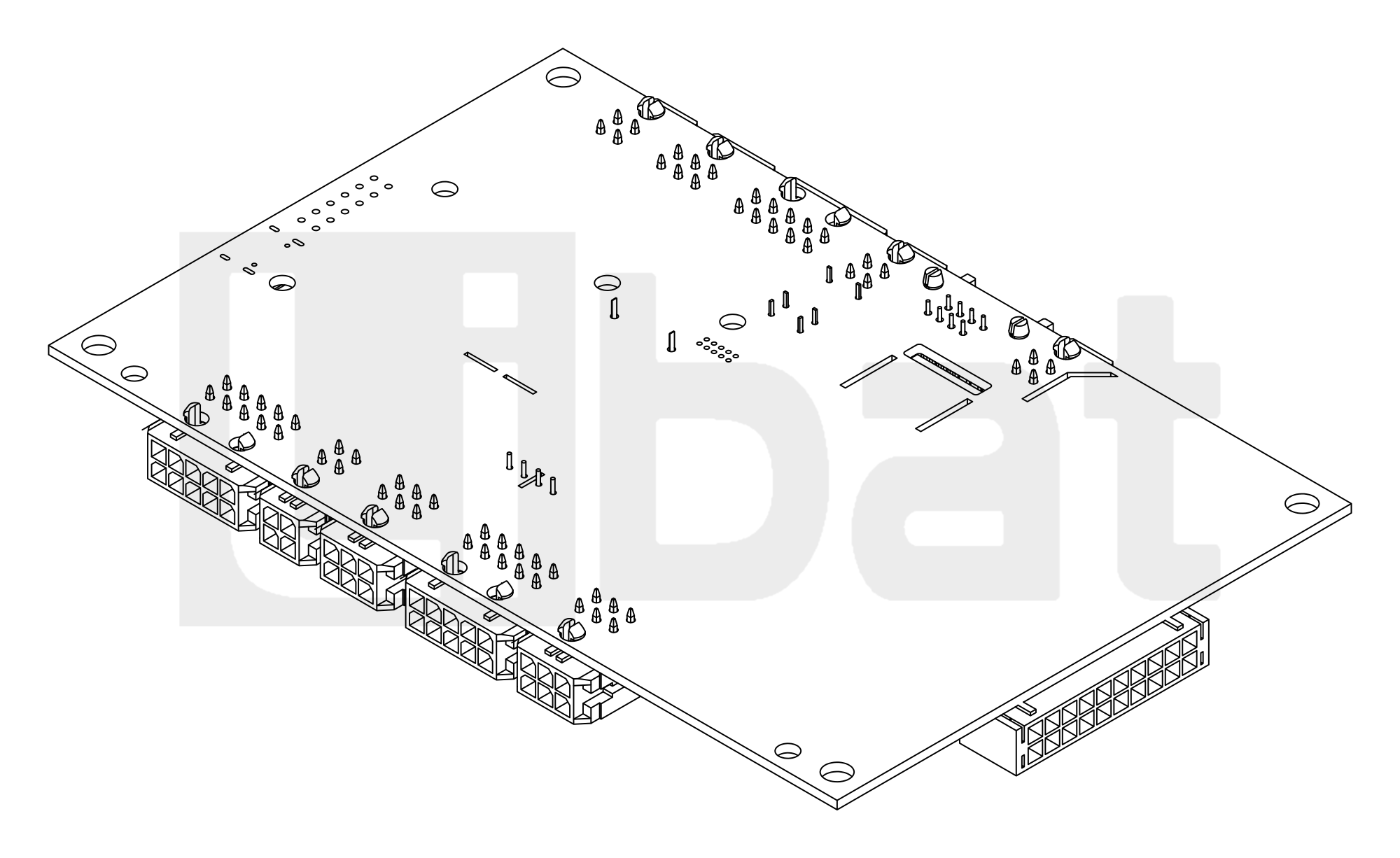
Table.1.1: BMS1820 Technical Specifications
| PARAMETER | SPECIFICATIONS |
|---|---|
| Power Source | Self powered from the pack (VIN+, 12-80Vdc) or external 12V supply (12Vin) |
| Power Consumption | Power Down: ~0.05 mW , RUN State: ~1345mW |
| Wake Up Trigger | User Button |
| LEDs | Power, Run/Error Status |
| Relays | 1x SPDT Relay Output |
| High Side Switch Outputs | 4x Automotive High-Side Switches for mini relays (12V internal or external supply on Vext) |
| Logic Inputs | 3x Isolated Logic Inputs |
| Logic Outputs | 2x Isolated TTL Outputs |
| RTC | Onboard RTC with backup battery |
| Slave Communication | Daisy-chain, 1x 1.5kV Isolated port (RJ45 or 4-pin connector) |
| Slave Module Support | Up to 14 slaves (BMS1802 / BMS1202) |
| Precharge | Configurable: disabled, time only, or time and current |
| DFU Mode | Embedded bootloader for firmware upgrades. |
| Digital Interface-1 | 1x Isolated Half Duplex RS485 |
| Digital Interface-2 | 1x Isolated RS232 |
| Digital Interface-3 | 1x Isolated CANBus 2.0b |
| Communication Protocols | LiBat standard protocols, JSON, Modbus RTU |
| Current Sensor | Compatible with 5V external current sensors (dual channel) |
| Operating Modes | Standalone, Master, Multi-Master |
| Number of cells | Up to 18 Cells (5S - 18S) on the board |
| Cell Type | Any battery cell in voltage range |
| Minimum cell voltage | 250 mV |
| Maximum cell voltage | 4500 mV |
| Accuracy of Cell Voltage Measurement | ±1.6mV typical, < ±8.3mV max. |
| Balance Method | Passive Balancing |
| Balance Current | 420mA @ 4.2Vdc cell voltage |
| Balance Power | 2W max. per cell |
| Temperature Sensor Type | NTC, 10KΩ @ 25 °C |
| Temperature Sensor Accuracy | ±1.5 °C (depends on sensor sensitivity) |
| Number of Temperature Sensor | Up to 5 external sensor probes, 1 x On board NTC |
| Operating Temperature | -20 °C to +70 °C (-4° F to +158° F) |
| Relative Humidity | 5% to 95% (non-condensing) |
| Expandability | Up to 270 cells total with slave modules |
| Dimensions | 138 mm X 90 mm X 18.6 mm |