2. INT101 Pinouts and Descriptions
INT101 carries its connector to the BMS (1) on the bottom side and the antenna connectors (2, 3), the nanoSIM holder (4), the status LEDs (5) and the GNSS module with its antenna (6) on the top. The numbers below are used on every page of the INT101.
Warning
Fit or remove the INT101 only after every cell connector and the supply connector of the BMS are unplugged, and insert or remove the SIM card only while the INT101 is off. Connect the GSM antenna before the INT101 is powered.
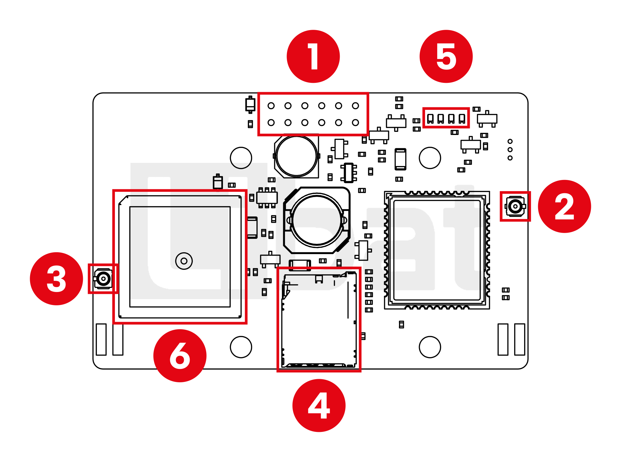
Table.2.1: Connector No#1, #2, #3, #4, #5, #6 Descriptions
| Connector No. | Pin No. | Description (see Fig.2.1) |
|---|---|---|
| 1 | - | BMS connector: 2 x 6 socket (female) on the bottom side; plugs onto the pin header of the BMS extension port and carries the 12 V supply, the power control and the serial ports of the modem and the GNSS module (see 3. Connection) |
| 2 | - | GSM antenna connector (uFL) for the GSM antenna |
| 3 | - | GNSS antenna connector (uFL) for an optional external active GNSS antenna; the INT101 uses it as soon as one is connected |
| 4 | - | nanoSIM card holder (push-push) |
| 5 | - | Status LEDs (blue), from left to right: power, GNSS fix, network, transmit (see 4. Operation) |
| 6 | - | GNSS module with its ceramic antenna on top; keep the space above it free of metal |