5. INT101 Board Dimensions
Use the dimensions below for the mechanical design and assembly.
Info
All dimensions are in mm unless stated otherwise.
Info
Simplified STEP or STP files are available upon request.
Warning
Check the mounting hole positions before you drill. Do not bend or strain the board during installation; this can damage it permanently.
Warning
Use only the mounting holes H1–H4 (red dotted circles, Table.5.1). On the BMS the INT101 sits on snap-in spacers in these holes, four on the BMS1810 and three on the other boards (3.2 Mounting on the BMS).
Fig.5.1: INT101, Board Dimensions (TOP)
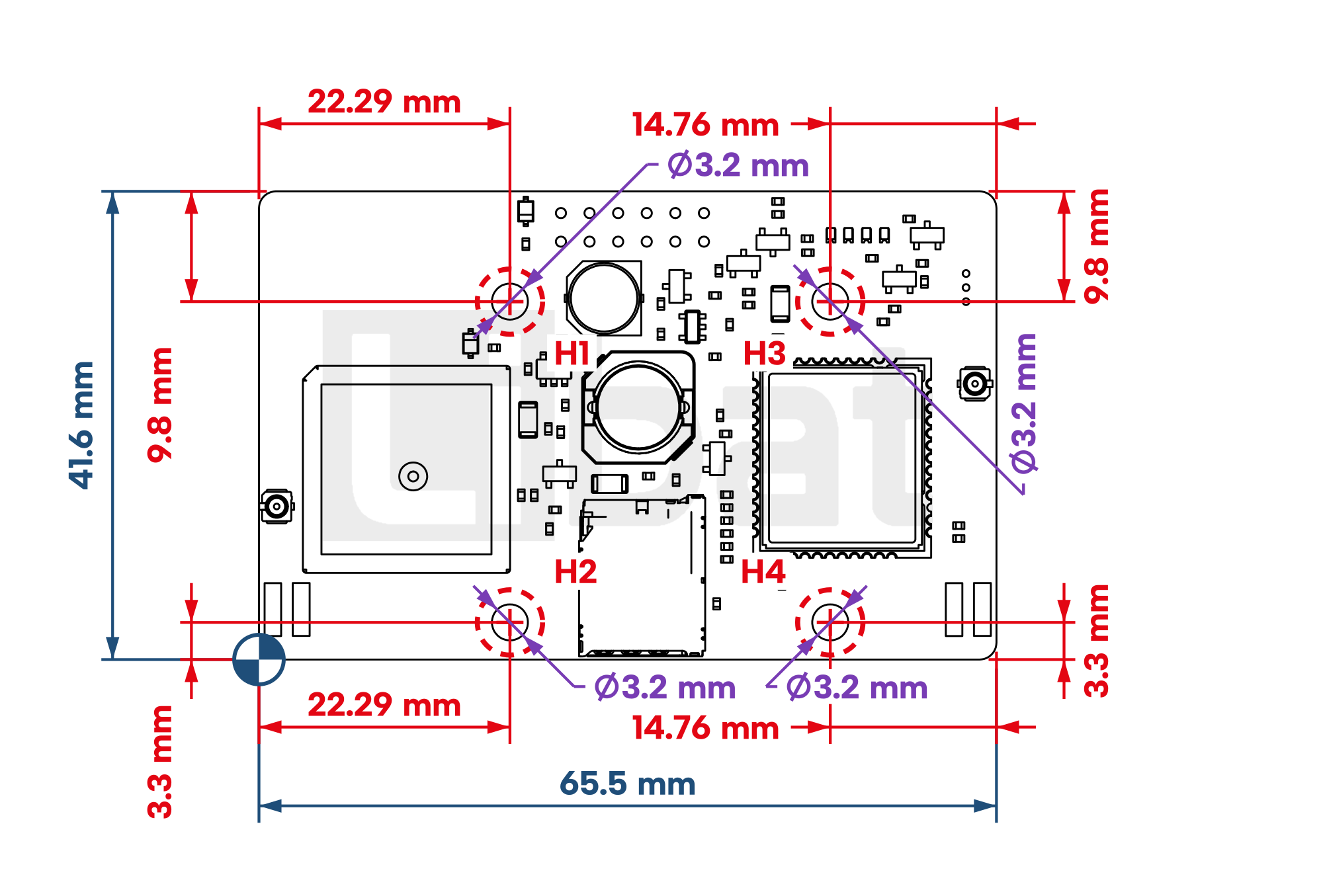
Fig.5.2: INT101, Board Dimensions (FRONT)
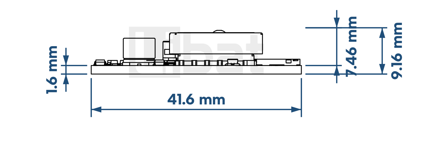
Table.5.1: Mounting Holes
| Hole | X (mm) | Y (mm) | Diameter (mm) |
|---|---|---|---|
| H1 | 22.29 | 31.8 | 3.2 |
| H2 | 22.29 | 3.3 | 3.2 |
| H3 | 50.74 | 31.8 | 3.2 |
| H4 | 50.74 | 3.3 | 3.2 |
X and Y are measured from the origin mark at the lower left corner of the box around the board in Fig.5.1.
Info
The drawings leave out the 2 x 6 socket on the bottom side (connector 1), which plugs onto the pin header of the BMS extension port. Keep the space above the GNSS module free of metal, and plan room for the antenna cables on connectors 2 and 3.
Danger
Take care not to damage the components on the board with mounting tools. A tool of the wrong size can damage the board permanently.