3. BMS1601 Battery Connection
BMS1601 measures 6 to 16 cells and switches the pack itself: the charge and discharge MOSFETs and the shunt that measures the current are on the board, so the battery and the load connect straight to its power terminals; the board itself takes its supply on connector 9. It has no slave modules. This page first shows the BMS1601 in a typical battery system, then the power terminals and the MOSFET path, charger detection and short circuit, the supply and the button, the cells, the temperature sensors, the communication ports, the outputs and inputs and the devices on the communication lines, and what to set in LiMon™ afterwards. The connector numbers and the terminal letters are those of the pinout.
3.1 BMS1601 in a Battery System
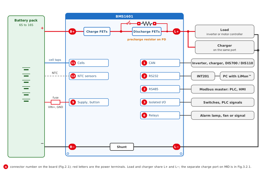
In a typical system the battery connects to B+ and B−, the load and the charger to L+ and L−, and the board takes its own supply from the pack through a fuse on connector 9. The BMS1601 measures the cells and the temperatures of the pack, measures the current on its shunt and opens or closes the charge and discharge MOSFETs between B+ and L+. It talks to the inverter, the charger and a DIS700 or DIS110 display over CAN, to a PC with LiMon™ over the service port and to a Modbus master over RS485; its isolated inputs and outputs and its two relays connect switches, signals and alarms.
Fig.3.1.1: BMS1601 in a Typical Battery System
3.2 Power Terminals and the MOSFET Path
On the board, B+ goes through the charge MOSFETs to the middle point MID and through the discharge MOSFETs to L+; the shunt is between B− and L−. Load and charger can share L+ and L− (A in Fig.3.2.1), or the charger connects to MID and L− as a separate charge port, so that the discharge MOSFETs switch only the load (B). Every current of the pack must return through L−: a load or a charger on B− bypasses the shunt and the BMS does not measure it. The shunt needs no wiring or setting; keep the default coefficient and correct it only by calibration (User Manual 3.6 Current Measurement).
Fig.3.2.1: BMS1601 Power Terminals and MOSFET Path
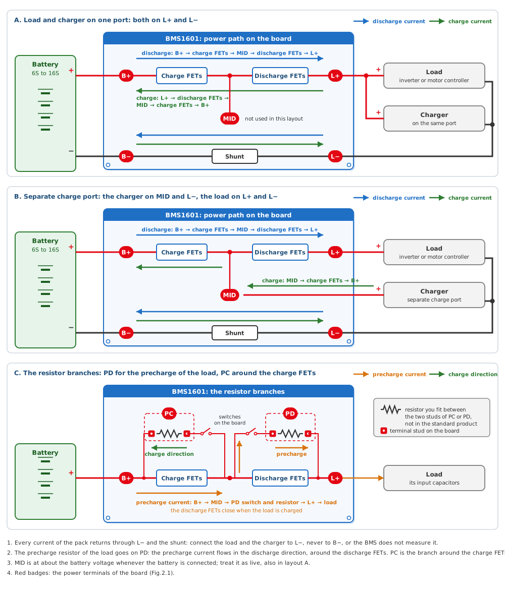
Each resistor branch has two studs on the board, and the resistor goes between them (C in Fig.3.2.1). The precharge of the load runs in the discharge direction, so its resistor goes on the PD studs, around the discharge MOSFETs: during the precharge the BMS closes this branch first and charges the input capacitors of the load through the resistor, then closes the discharge MOSFETs. The PC studs take a resistor around the charge MOSFETs, in the charge direction. Neither resistor is fitted in the standard product. The precharge settings are in User Manual 3.9 Precharge.
Danger
B+, MID and PC are at battery voltage whenever the battery is connected, also while the MOSFETs are off. Connect the battery last and treat every power terminal as live.
3.3 Charger Detection and Short Circuit
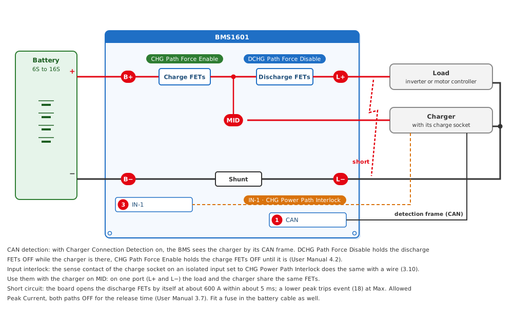
With the charger on MID, the BMS1601 can keep the load off while the pack charges and keep the charge path OFF while no charger is connected. It learns that a charger is there in one of two ways. With Charger Connection Detection on, it sees the charger by a frame that the charger sends on CAN; DCHG Path Force Disable then holds the discharge MOSFETs OFF while the charger is detected, and CHG Path Force Enable holds the charge MOSFETs OFF until it is (User Manual 4.2 Charger Integration). Without CAN, the sense contact of the charge socket goes to an isolated input set to CHG Power Path Interlock (User Manual 3.10 Inputs and Outputs). Use these options with the separate charge port: with load and charger on one port both pass the same MOSFETs.
The cell monitor of the board can also see a charger or a load plugged in on L+ while the board is in a low-power standby. The current firmware does not put the BMS1601 into that standby, so the board starts only with the user button.
A short circuit on the load side is cut by the board itself: the discharge MOSFETs open at about 600 A within about 5 ms. A lower peak that reaches Max. Allowed Peak Current trips event (18) Short Circuit Protection, which switches both paths OFF for its release time (User Manual 3.7 Current Limits). Fit a fuse in the battery cable as well, rated for the cells and the cables.
Fig.3.3.1: BMS1601 Charger Detection and Short Circuit
Warning
After event (18) the BMS switches the paths on again by itself after the release time. Disconnect the load and repair the short first (6.1 Events and What to Do).
3.4 Power Supply and User Button
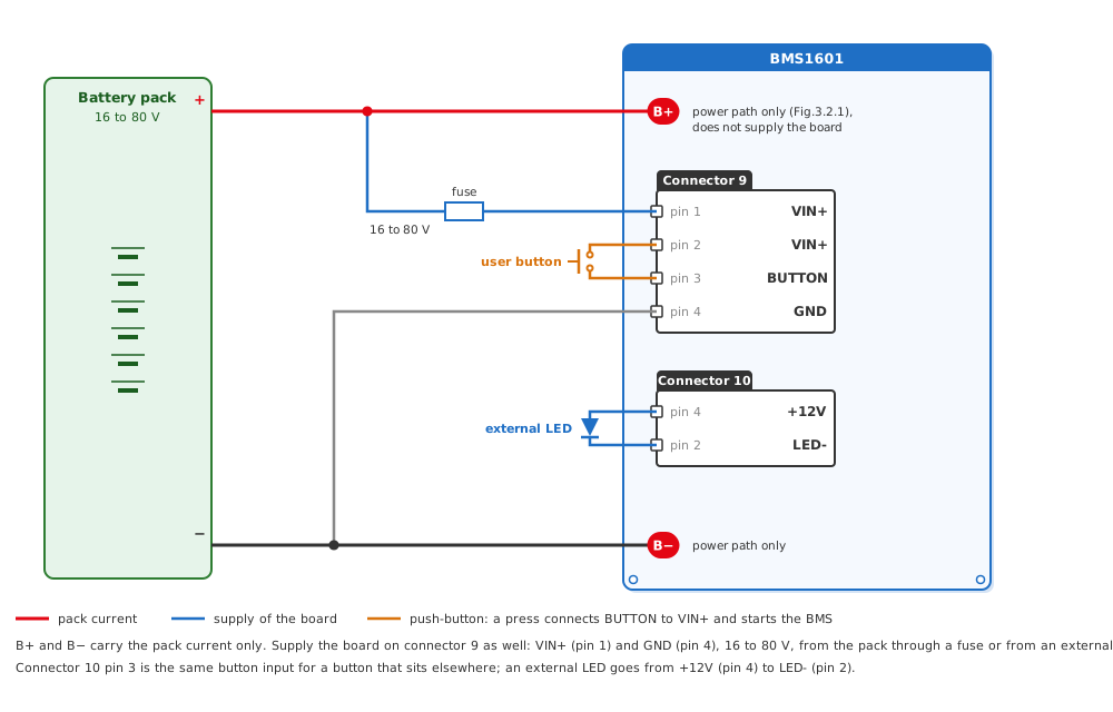
The power terminals B+ and B− carry only the pack current; they do not supply the board. Supply the BMS1601 on connector 9 as well: VIN+ on pin 1 and GND on pin 4, 16 to 80 V, from the pack through a fuse or from an external supply. The board starts with a press of the user button, a push-button between VIN+ (connector 9 pin 2) and BUTTON (pin 3); connector 10 pin 3 is the same button input for a button that sits elsewhere, and an external LED goes from +12V (connector 10 pin 4) to LED- (pin 2).
Fig.3.4.1: BMS1601 Supply and User Button
Warning
With only B+ and B− connected the board stays off: it needs VIN+ and GND on connector 9.
Tip
What the button does after the start, and how the BMS shuts itself down, is in User Manual 3.11 Button and Shutdown.
3.5 Cell Connection
Warning
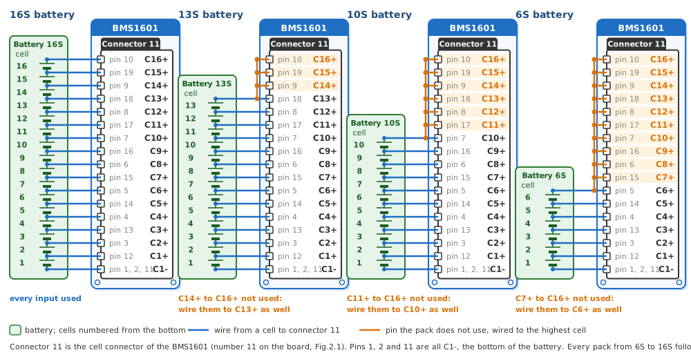
Take C1- and the tap of the top cell on wires of their own, not from the B+ and B− power cables. A wire shared with the load current drops voltage and gives wrong cell readings.
Info
Tie the unused inputs to the highest cell, on the cell measurement cable or at the connector; open inputs give wrong cell measurements.
Fig.3.5.1: BMS1601 6S to 16S Battery Cell Connections
Tip
After the wiring, check the cell count as 3.10 describes.
3.6 Temperature Sensor Connection
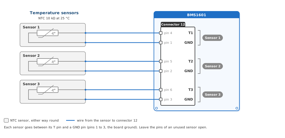
Up to three NTC sensors connect to connector 12, each between its T pin (pins 4 to 6) and a GND pin (pins 1 to 3); in LiMon™ Live View they are T1 to T3. The board also measures the temperature of its MOSFETs itself, for the FET O.T. limits of User Manual 3.5 Temperature Limits.
Fig.3.6.1: BMS1601 Temperature Sensor Connection
Tip
Leave the pins of an unused sensor open: an input without a sensor is ignored. Check in Live View that every connected sensor reads a value.
3.7 Communication Ports and Termination Switch
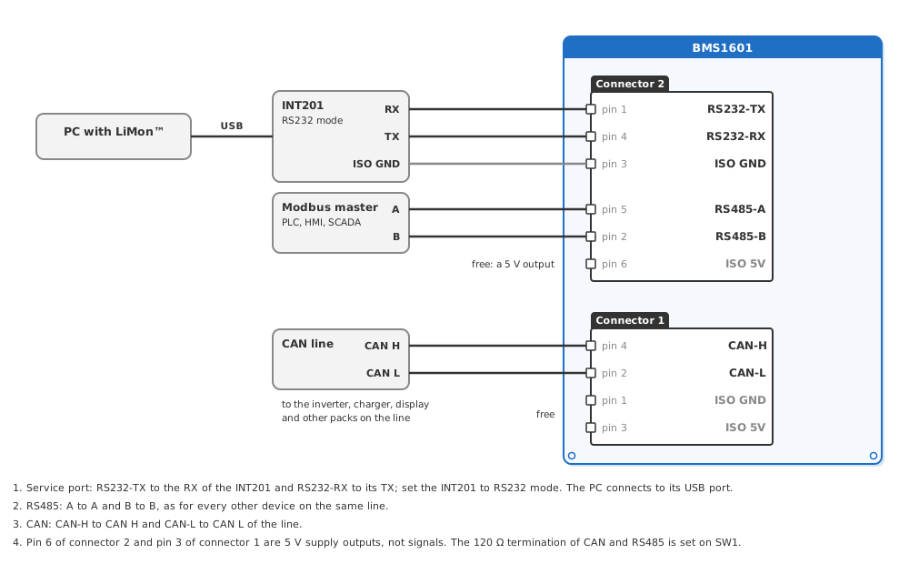
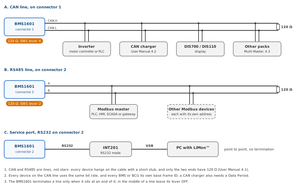
RS232 (the service port for LiMon™) and RS485 are on connector 2, CAN on connector 1, all isolated from the battery. The service port goes to a PC through an INT201 with its transmit and receive lines crossed, RS485 connects A to A and B to B. The settings of the ports are in User Manual 4.1 Communication Ports.
Fig.3.7.1: BMS1601 Communication Port Wiring
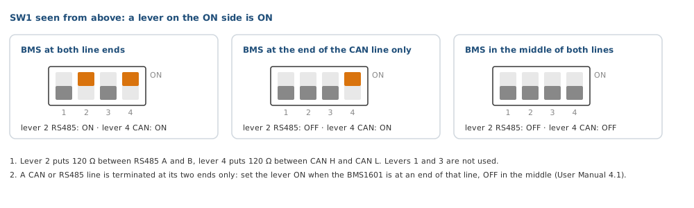
CAN and RS485 are lines with a 120 Ω termination at each of their two ends. The termination switch SW1 (number 13 on the board) has one lever for each line: lever 2 terminates RS485, lever 4 terminates CAN, levers 1 and 3 are not used. Set a lever ON only when the BMS1601 sits at an end of that line.
Fig.3.7.2: BMS1601 Termination Switch SW1
3.8 Outputs and Inputs
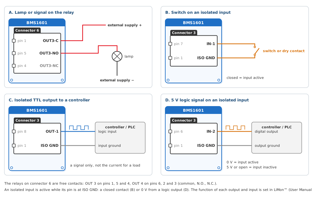
The two relays on connector 6 (OUT 3 and OUT 4) are free contacts (COM, N.O., N.C.) for lamps, fans or signals. Connector 3 carries the three isolated inputs and the isolated TTL outputs OUT 1 and OUT 2 with their own ISO GND on pins 1 to 4: an input is active while it is at ISO GND, through a closed contact or a 0 V logic signal (5 V or open is inactive), and a TTL output gives a signal, not the current for a load. The charge and discharge paths need no output: the MOSFETs on the board switch them. What each output and input does is set in LiMon™; see User Manual 3.10 Inputs and Outputs, whose Table.3.10.4 lists the pin of every LiMon™ number.
Fig.3.8.1: BMS1601 Output and Input Examples
3.9 Devices on the Communication Lines
The CAN line on connector 1 carries the inverter or motor controller, a CAN charger, a DIS700 or DIS110 display and, in a system with packs in parallel, the other packs. The RS485 line on connector 2 carries a Modbus master, such as a PLC, an HMI, a SCADA system or a gateway, and any other Modbus device with its own address. The service port is a point-to-point link to a PC with LiMon™ through an INT201. A charger on CAN is set up as in User Manual 4.2 Charger Integration, packs in parallel as in User Manual 4.3 Parallel Packs.
Fig.3.9.1: BMS1601 Devices on the Communication Lines
3.10 Settings in LiMon™ and First Check
After the wiring, set the cells in LiMon™ and restart the BMS so that it finds them:
- Module ID#0: the cell count measured on connector 11 (6 to 16). BMS1601 has no slave modules; leave Slave Module Type Selection at --- (User Manual 3.1 Battery Topology).
- Save, restart the BMS and check in Live View that the module is there with the cell count you set. The full procedure is in 2.1 Commissioning Checklist.
Table.3.10.1: Wiring Faults and What the BMS Reports
| Wiring fault | Event | What to check |
|---|---|---|
| A cell tap missing or loose, an unused input not tied to the highest cell, or a cell count in LiMon™ that does not match | (26) Cell Connection Error | Connected Cells of the module, then connector 11 and the cell count in LiMon™ |
| A temperature sensor not connected or its wire broken | none; the input is ignored | That the sensor reads a value in Live View |
| A load or charger negative on B− instead of L− | none; that current is not measured | The pack current in Live View while the load or the charger runs |
| Only B+ and B− connected, no supply on connector 9 | none; the board does not start | VIN+ (pin 1) and GND (pin 4) of connector 9 |
After a fault is repaired, restart the BMS. All events and their causes are in 6.1 Events and What to Do.