2. BMS1820 Pinouts and Descriptions
BMS1820 measures up to 18 cells on connector 1 and drives the slave modules over the isolated daisy chain (RJ45 connector 14 or 4-pin connector 15). Power and the button come in on connectors 10 and 11, the current sensor and the temperature sensors on connectors 2 and 3, the communication ports on connectors 4 and 5, and the inputs and outputs on connectors 6, 12 and 13. Arrange the cables with the pinouts below; a number in the figures opens the table of that connector.
Danger
Check every connection and cable before you plug a connector into the BMS1820.
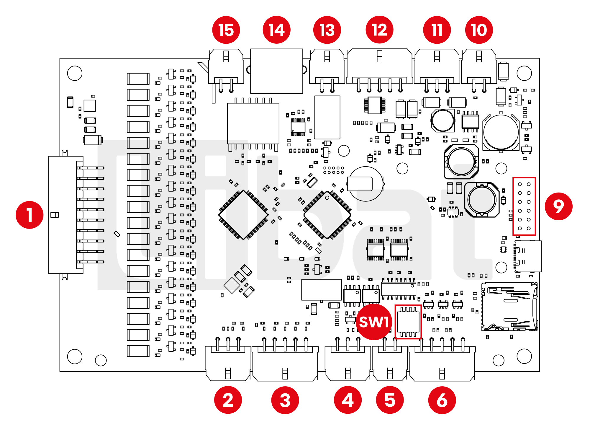
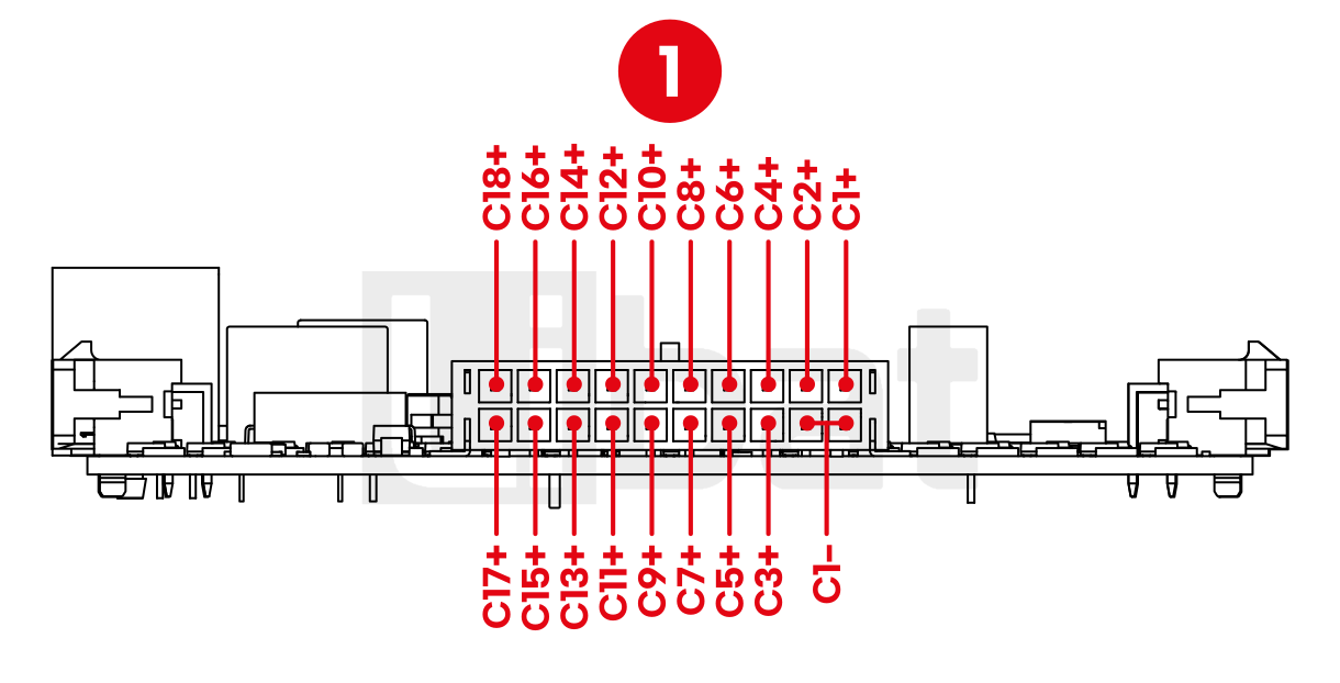
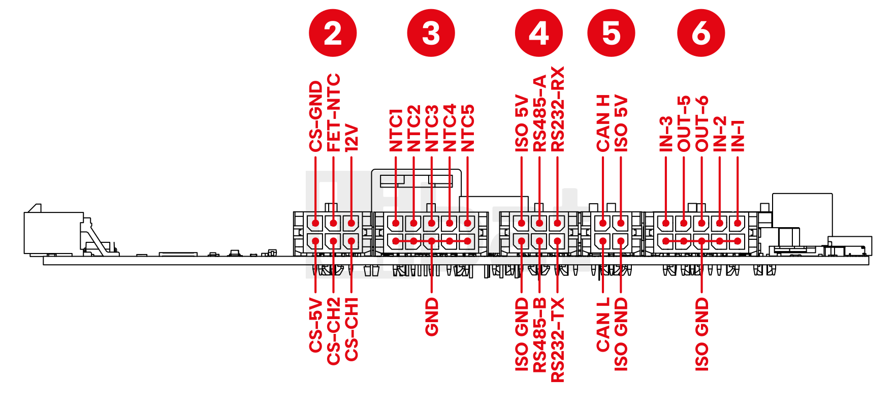
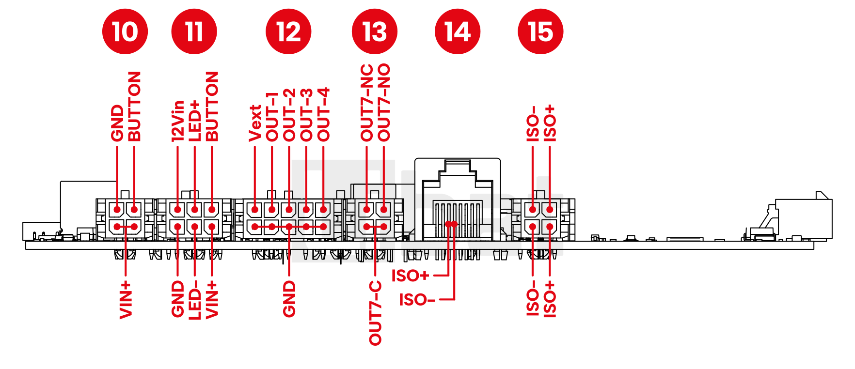
Table.2.1: Connector No#1 Descriptions
| Connector No. | Pin No. | Description (see Fig.2.1 and Fig.2.2) |
|---|---|---|
| 1 | 1, 2 | Bottom of the battery string, 1st cell's negative tab (C1-) |
| 1 | 3 | 3rd cell's positive tab (C3+) |
| 1 | 4 | 5th cell's positive tab (C5+) |
| 1 | 5 | 7th cell's positive tab (C7+) |
| 1 | 6 | 9th cell's positive tab (C9+) |
| 1 | 7 | 11th cell's positive tab (C11+) |
| 1 | 8 | 13th cell's positive tab (C13+) |
| 1 | 9 | 15th cell's positive tab (C15+) |
| 1 | 10 | 17th cell's positive tab (C17+) |
| 1 | 11 | 1st cell's positive tab (C1+) |
| 1 | 12 | 2nd cell's positive tab (C2+) |
| 1 | 13 | 4th cell's positive tab (C4+) |
| 1 | 14 | 6th cell's positive tab (C6+) |
| 1 | 15 | 8th cell's positive tab (C8+) |
| 1 | 16 | 10th cell's positive tab (C10+) |
| 1 | 17 | 12th cell's positive tab (C12+) |
| 1 | 18 | 14th cell's positive tab (C14+) |
| 1 | 19 | 16th cell's positive tab (C16+) |
| 1 | 20 | Top of the battery string, 18th cell's positive tab (C18+) |
Table.2.2: Connector No#2 Descriptions
| Connector No. | Pin No. | Description (see Fig.2.1 and Fig.2.3) |
|---|---|---|
| 2 | - | Current Sensor Connector |
| 2 | 1 | Current Sensor CH1 Sense Input |
| 2 | 2 | Current Sensor CH2 Sense Input |
| 2 | 3 | 5V Output for Current Sensor Power |
| 2 | 4 | 12V Output |
| 2 | 5 | FET Temperature Sensor Input (NTC), not used by the current firmware |
| 2 | 6 | GND for Current Sensor Power |
Table.2.3: Connector No#3 Descriptions
| Connector No. | Pin No. | Description (see Fig.2.1 and Fig.2.3) |
|---|---|---|
| 3 | 1, 2, 3, 4, 5 | Ground (GND) of the temperature sensors |
| 3 | 6 | External Temperature Sensor No.5 (NTC5) |
| 3 | 7 | External Temperature Sensor No.4 (NTC4) |
| 3 | 8 | External Temperature Sensor No.3 (NTC3) |
| 3 | 9 | External Temperature Sensor No.2 (NTC2) |
| 3 | 10 | External Temperature Sensor No.1 (NTC1) |
Table.2.4: Connector No#4 Descriptions
| Connector No. | Pin No. | Description (see Fig.2.1 and Fig.2.3) |
|---|---|---|
| 4 | 1 | RS232 No.0 Transmit Data (Service Port) |
| 4 | 2 | RS485 B Pin |
| 4 | 3 | ISO- GND |
| 4 | 4 | RS232 No.0 Receive Data (Service Port) |
| 4 | 5 | RS485 A Pin |
| 4 | 6 | ISO-5V Output |
Table.2.5: Connector No#5 Descriptions
| Connector No. | Pin No. | Description (see Fig.2.1 and Fig.2.3) |
|---|---|---|
| 5 | 1 | ISO- GND |
| 5 | 2 | CAN 2.0b CH1 Low Pin (CAN L) |
| 5 | 3 | ISO-5V Output |
| 5 | 4 | CAN 2.0b CH1 High Pin (CAN H) |
Table.2.6: Connector No#6 Descriptions
| Connector No. | Pin No. | Description (see Fig.2.1 and Fig.2.3) |
|---|---|---|
| 6 | 1, 2, 3, 4, 5 | ISO GND |
| 6 | 6 | Isolated Input 1 (LiMon INPUT 1) |
| 6 | 7 | Isolated Input 2 (LiMon INPUT 2) |
| 6 | 8 | Isolated Output 2 (LiMon OUT 6) |
| 6 | 9 | Isolated Output 1 (LiMon OUT 5) |
| 6 | 10 | Isolated Input 3 (LiMon INPUT 3) |
Table.2.7: Connector No#9 Descriptions
| Connector No. | Pin No. | Description (see Fig.2.1) |
|---|---|---|
| 9 | - | Port for LiBat Extension Board |
Table.2.8: Connector No#10 Descriptions
| Connector No. | Pin No. | Description (see Fig.2.1 and Fig.2.4) |
|---|---|---|
| 10 | 1, 2 | Board VIN+ (Board Main Power) |
| 10 | 3 | External Button Input, a push-button to VIN+ (pin 2) starts the BMS |
| 10 | 4 | Board GND (Board Main Power) |
Table.2.9: Connector No#11 Descriptions
| Connector No. | Pin No. | Description (see Fig.2.1 and Fig.2.4) |
|---|---|---|
| 11 | 1 | Board VIN+ Output |
| 11 | 2 | External LED- Output (LED GND) |
| 11 | 3 | Board GND |
| 11 | 4 | External Button Input, a push-button to VIN+ (pin 1) starts the BMS |
| 11 | 5 | External LED+ Output |
| 11 | 6 | +12V Supply Input (12Vin), never together with VIN+ on connector 10 |
Table.2.10: Connector No#12 Descriptions
| Connector No. | Pin No. | Description (see Fig.2.1 and Fig.2.4) |
|---|---|---|
| 12 | - | High-Side Switch Outputs, for mini relays, not for contactor coils |
| 12 | 1, 2, 3, 4, 5 | GND |
| 12 | 6 | High-Side Switch Output (LiMon OUT 4) |
| 12 | 7 | High-Side Switch Output (LiMon OUT 3) |
| 12 | 8 | High-Side Switch Output (LiMon OUT 2) |
| 12 | 9 | High-Side Switch Output (LiMon OUT 1) |
| 12 | 10 | External Supply Input of the High-Side Switches (Vext) |
Table.2.11: Connector No#13 Descriptions
| Connector No. | Pin No. | Description (see Fig.2.1 and Fig.2.4) |
|---|---|---|
| 13 | 1, 2 | Relay Common Pin (LiMon OUT 7) |
| 13 | 3 | Relay Normally Open Pin (LiMon OUT 7) |
| 13 | 4 | Relay Normally Closed Pin (LiMon OUT 7) |
Table.2.12: Connector No#14, #15 Descriptions
| Connector No. | Pin No. | Description (see Fig.2.1 and Fig.2.4) |
|---|---|---|
| 14 | - | Isolated Daisy-Chain Connector (Standard RJ45) |
| 14 | 1, 2, 3, 4, 7, 8 | Not Connected |
| 14 | 5 | Isolated daisy-chain communication port (ISO-) |
| 14 | 6 | Isolated daisy-chain communication port (ISO+) |
| 15 | - | Isolated Daisy-Chain Connector (4-pin), the same lines as connector 14 |
| 15 | 1 | Isolated daisy-chain communication port (ISO+) |
| 15 | 2 | Isolated daisy-chain communication port (ISO-) |
| 15 | 3 | Isolated daisy-chain communication port (ISO+) |
| 15 | 4 | Isolated daisy-chain communication port (ISO-) |
Table.2.13: SW1 Descriptions
| Part | Lever | Description (see Fig.2.1) |
|---|---|---|
| SW1 | - | CAN and RS485 Termination Switch: ON puts 120 Ω across the line, only at the two ends of a line |
| SW1 | 1 | Lever 1: not used |
| SW1 | 2 | Lever 2: RS485 termination, 120 Ω between RS485 A and B (connector 4 pins 5 and 2) |
| SW1 | 3 | Lever 3: not used |
| SW1 | 4 | Lever 4: CAN termination, 120 Ω between CAN H and CAN L (connector 5 pins 4 and 2) |