3. DIS110 Connection
DIS110 connects to one LiBat™ BMS on its connector 8: normally the BMS supplies it and its BMS button works as the button of the BMS, its BMS STAT LED is the status LED of the BMS, and the battery status comes over CAN. It can also run from a separate supply (3.3). This page gives the wiring for every master board and what to set in LiMon™.
3.1 Connector 8
Connector 8 carries four groups of lines. Supply: VIN+ on pins 5 and 10 and GND on pins 4 and 9 come from the BMS or from a separate supply (3.3); the DIS110 runs from 12 to 80 V and turns on when its BMS button or the button of the BMS is pressed, or always while lever 2 of DIP switch 9 is ON (4. Operation). Button: the BMS button connects VIN+ to pin 8, which goes to the button input of the BMS, so it starts the BMS like the button of the BMS itself; on a separate supply pin 8 stays open. BMS STAT LED: LED 4 sits between pin 7 (anode) and pin 2 (cathode) and is driven by the LED output of the BMS. CAN: CAN H on pin 1 and CAN L on pin 6. Pin 3 is not connected.
3.2 Wiring to a BMS
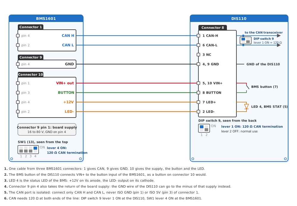
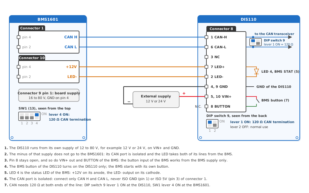
Fig.3.2.1 to Fig.3.2.5 give the BMS pin for every pin of connector 8; the connector numbers are those of the pinout page of each board. On BMS1820, BMS3610, BCU2002 and BMS1601 the CAN port is isolated: connect only CAN H and CAN L, never its ISO GND, so that the port stays isolated; the DIS110 takes its GND from a board GND pin of the BMS, as in the figures. The figures show the termination at both ends, for a line with these two devices only.
Fig.3.2.1: DIS110 on a BMS1810
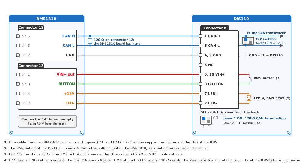
Fig.3.2.2: DIS110 on a BMS1820
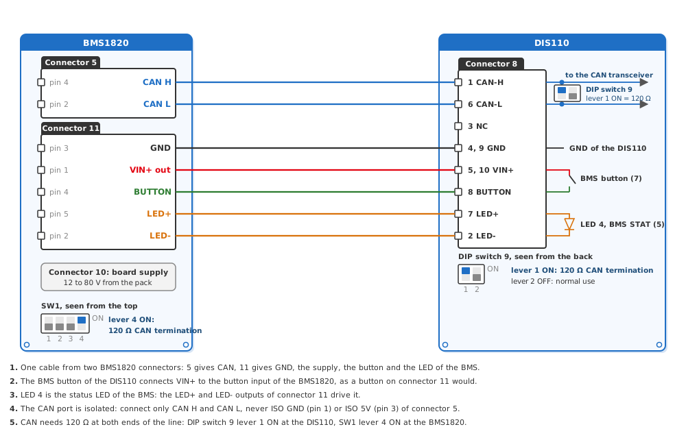
Fig.3.2.3: DIS110 on a BMS3610
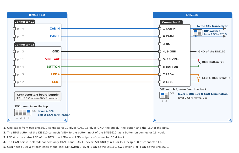
Fig.3.2.4: DIS110 on a BCU2002
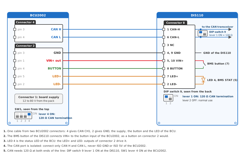
Fig.3.2.5: DIS110 on a BMS1601
3.3 Wiring with a Separate 12 V or 24 V Supply
The DIS110 can also run from a supply of its own, for example 12 V or 24 V (12 to 80 V), so that it takes nothing from the supply of the BMS. This is also the way when a BMS1820, BMS3610 or BCU2002 runs from 12Vin: VIN+ out then carries no supply, and the DIS110 takes the same 12 V. Then the plus of that supply goes to VIN+ (pins 5 and 10) and its minus to GND (pins 4 and 9). On BMS1820, BMS3610, BCU2002 and BMS1601 the minus does not go to the BMS: their CAN port is isolated and the LED takes both of its lines from the BMS. The CAN port of the BMS1810 is not isolated, so there the minus also goes to GND of the BMS1810 (connector 12 pin 2). Pin 8 stays open, and so do VIN+ out and BUTTON on the BMS: the button input of the BMS works from the supply of the BMS only. The BMS button of the DIS110 then turns on the DIS110 only, and the BMS starts with its own button; with lever 2 of DIP switch 9 ON the DIS110 stays on while its supply is on. CAN, the LED and the termination stay as in 3.2. Fig.3.3.1 to Fig.3.3.5 show the wiring for each board.
Fig.3.3.1: DIS110 on a BMS1810 with a Separate Supply
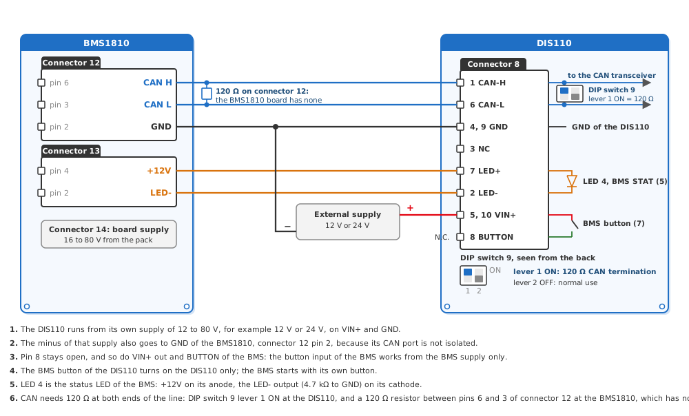
Fig.3.3.2: DIS110 on a BMS1820 with a Separate Supply
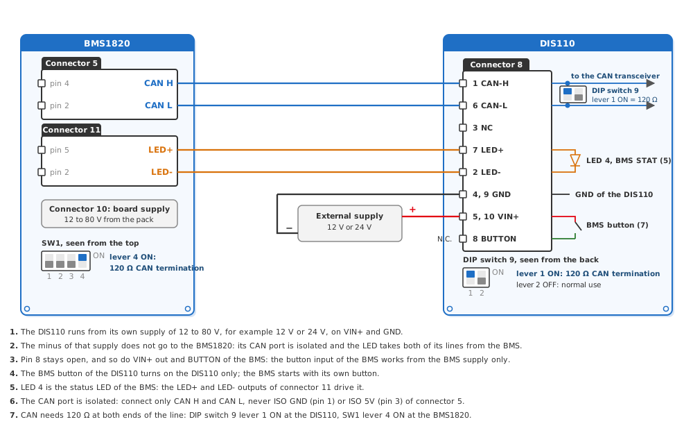
Fig.3.3.3: DIS110 on a BMS3610 with a Separate Supply
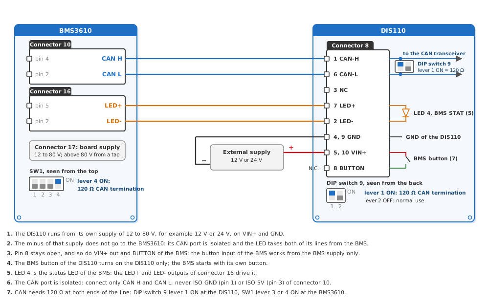
Fig.3.3.4: DIS110 on a BCU2002 with a Separate Supply
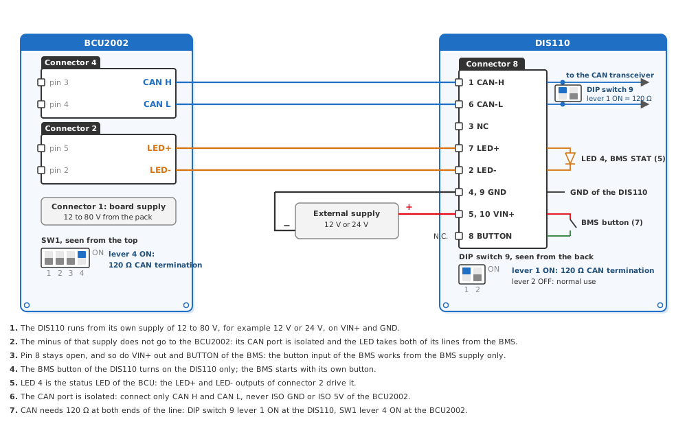
Fig.3.3.5: DIS110 on a BMS1601 with a Separate Supply
3.4 CAN Line and Termination
The DIS110 is one more device on the CAN line of the BMS, next to the inverter or the charger. A CAN line has a 120 Ω termination at each of its two ends: set lever 1 of the DIP switch (connector 9) ON only when the DIS110 sits at an end of the line, and OFF when it sits between other devices. Lever 2 keeps the DIS110 on while it has supply; leave it OFF for normal use (4. Operation).
3.5 Settings in LiMon™
The DIS110 reads the frames of the LiBat™ CAN protocol v2. Set on the BMS, in LiMon™ Interface Settings: CANBus CH#1 Protocol to LiBat CANbus v2.0, and CANBus CH#1 Data Period to a period, so that the BMS sends its frames by itself. The DIS110 expects the default CANBus CH#1 Base Frame ID 0x0AAA and finds the bit rate by itself; a BMS with another base frame ID, or one that sends no frames, needs the matching setting in the web interface of the DIS110, which the DIS110 user manual describes. The settings are explained in User Manual 4.1 Communication Ports.
Tip
After the wiring, start the BMS; on a separate supply, turn on the DIS110 with its BMS button as well. The LED bar plays a short animation, then the CAN LED (LED 3) blinks and the bar shows the state of charge. If the CAN LED stays off, the DIS110 gets no battery status: check the CAN wiring, the termination and the settings above.
Danger
Check every connection and cable before you plug a connector into the DIS110 or the BMS.