4. BMS1202 Battery Connection
BMS1202 is designed for between 5S to 12S battery systems. However, user need to arrange signal and power cables for various series of battery pack. In this section, you can find the connection diagrams for 5S to 12S battery packs.
4.1 Power-Up Sequence
BMS1202 gets its own power from cell connection connector. There is no need to supply extra power and power cable for BMS. When you connect the cell connection properly, board powers on and does some inital start check. Then, it is ready to measure and communicate. RUN led will turn on after first cell connection then will turn off if any communication is not exist.
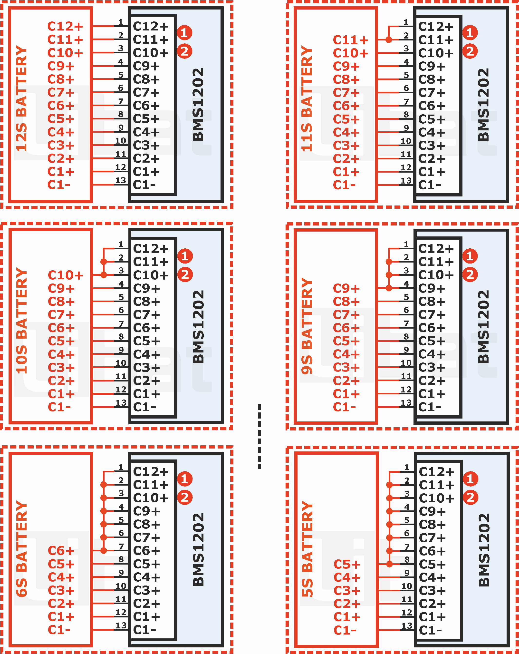
4.2 Cell Connection
Warning
Don't mix the power and cell voltage lines. Always separate the cell measurement ground (C1-) and power ground (B-). If you don't separate the cables from the source, unwanted sudden voltage drops may happen. This situation causes wrong cell measurements.
Warning
Always separate the top cell's positive signal (accroding to series in battery pack) and positive power output (B+). If you don't separate the cables from the source, unwanted sudden voltage drops may happen. This situation causes wrong cell measurements.
Info
User may arrange the shorted pins either on the cell measurement cable or jumpers on the board. Its up to user choice. For all type of connections, it is very important to short unused pins to highest cell of the battery pack for high quality measurements.
Fig.4.2.1: BMS1202 5S to 12S Battery Cell Connections
Tip
BMS1202 automatically detects how many cells connected to the board on power-up sequence. Reset after cell connection and see the connected cell count from PC software. If something goes wrong, try to fix the cables.
4.3 Temperature Sensor Connection
Fig.4.3.1: BMS1202 Temperature Sensor Connection
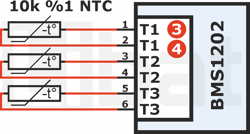
Tip
BMS1202 automatically detects how many temperature sensors connected to the board on power-up sequence. Unused pins shall short or leave float.
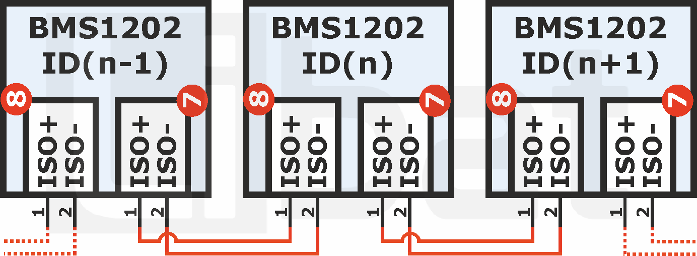
4.4 Master Connection via Isolated Daisy Chain Communication Port
BMS1202 has not smart firmware on its own. IT needs to be connected as slave to master via isolated daisy chain communication port. Master unit always commands to the BMS1202 slave module to measure and control the batteries connected to it. Every event are under control of master unit by using slave unit. But proper daisy chain connection must done by user.
Tip
BMS1202 has two port of daisy chain connection. ISO+ and ISO- pins must be connected one-to-one to another daisy chain communication port.
Fig.4.4.1: BMS1202 Isolated Daisy Chain Connection