2. BMS1202 Pinouts and Descriptions
On BMS1202 there are connectors for cell connections, temperature sensors, relay output, isolated daisy chain communication's top and bottom connectors. User must arrange the cable connections to any of these connectors by guides and pinouts below. Also there are four soldering jumper points to set ID of the board.
Danger
Make sure all the connections done correctly and double check the cables. Think twice before plug into any connectors on BMS1202.
Fig.2.1: BMS1202, Board Pinout (TOP)
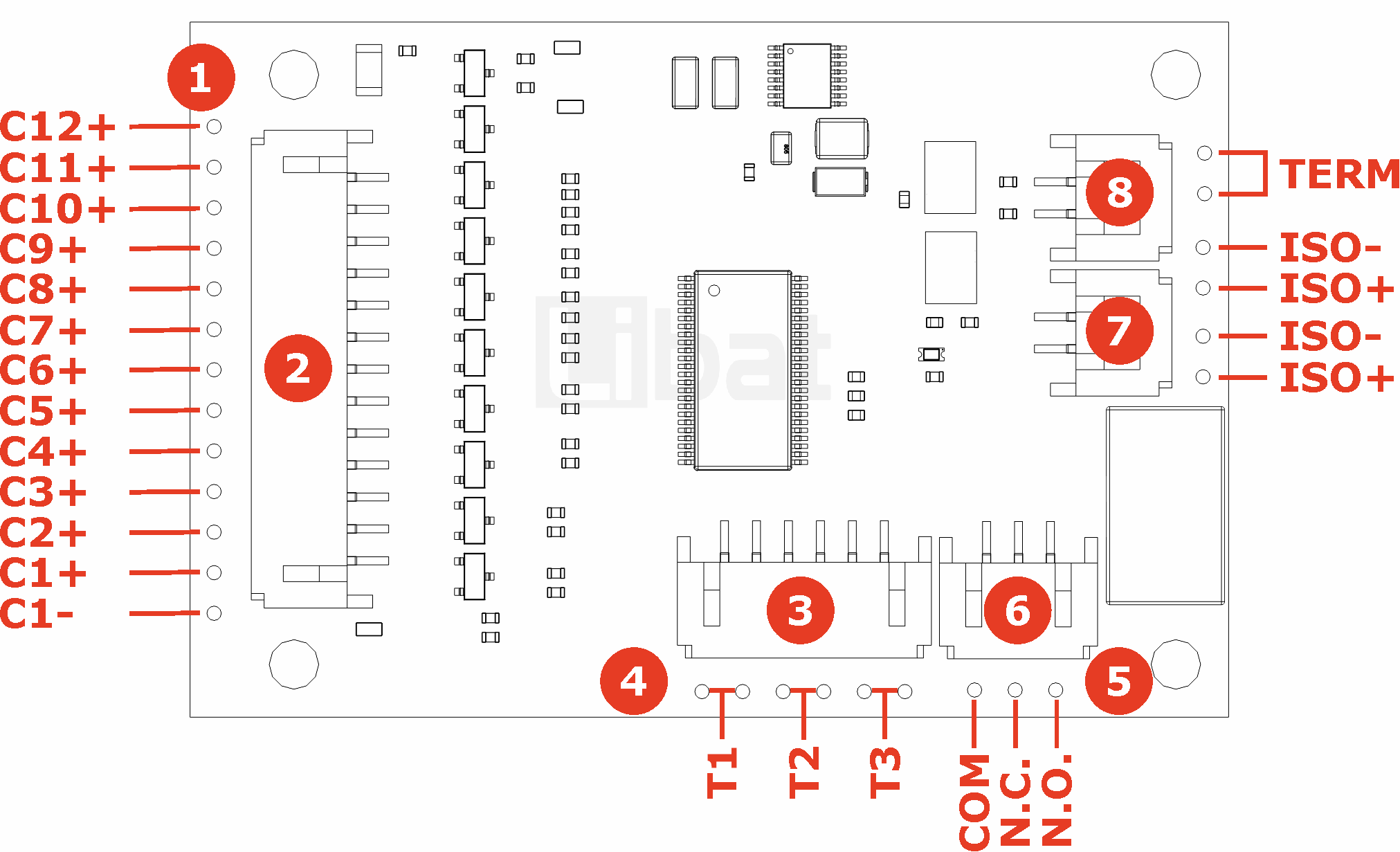
Fig.2.2: BMS1202, Board Pinout (LEFT)
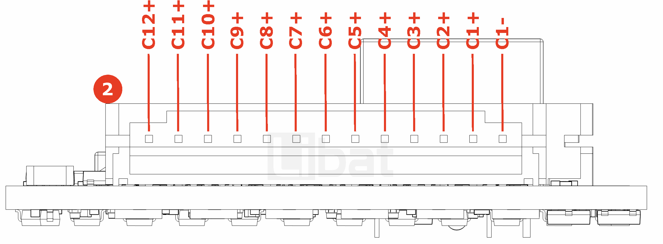
Fig.2.3: BMS1202, Board Pinout (FRONT)
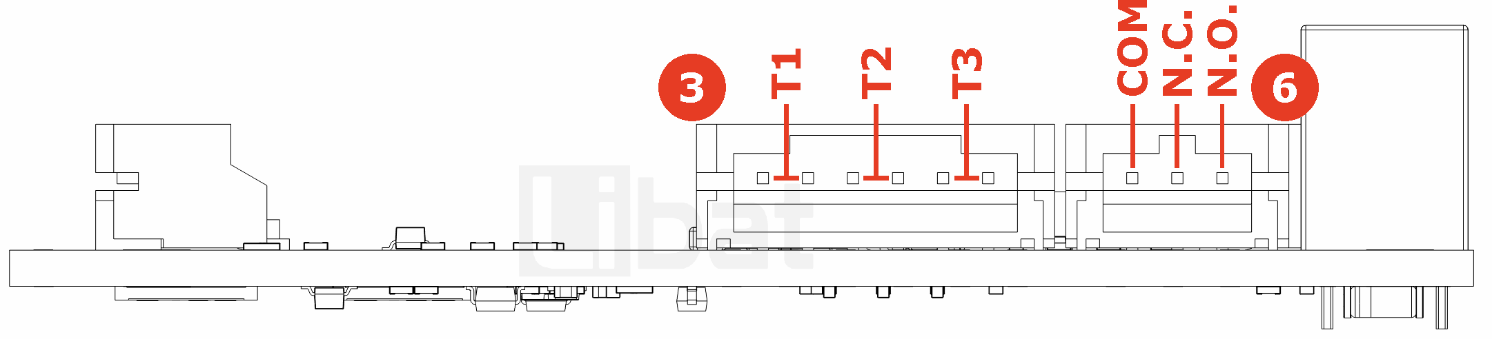
Fig.2.4: BMS1202, Board Pinout (RIGHT)
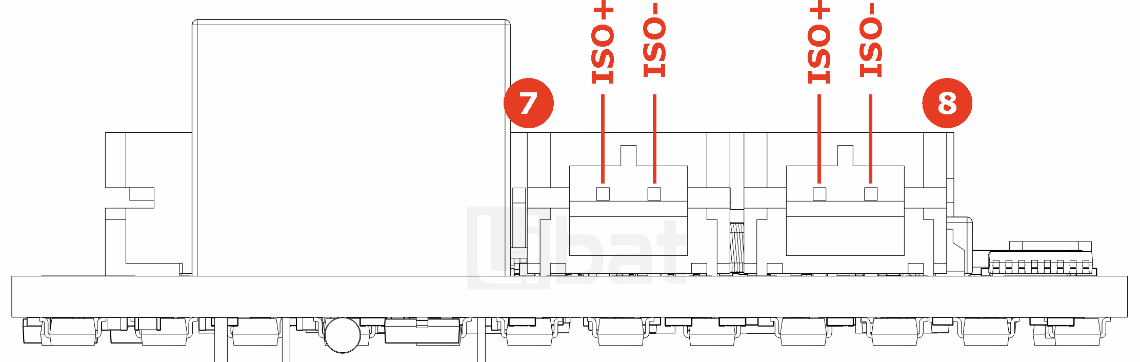
Fig.2.5: BMS1202, Board Pinout (BOTTOM)
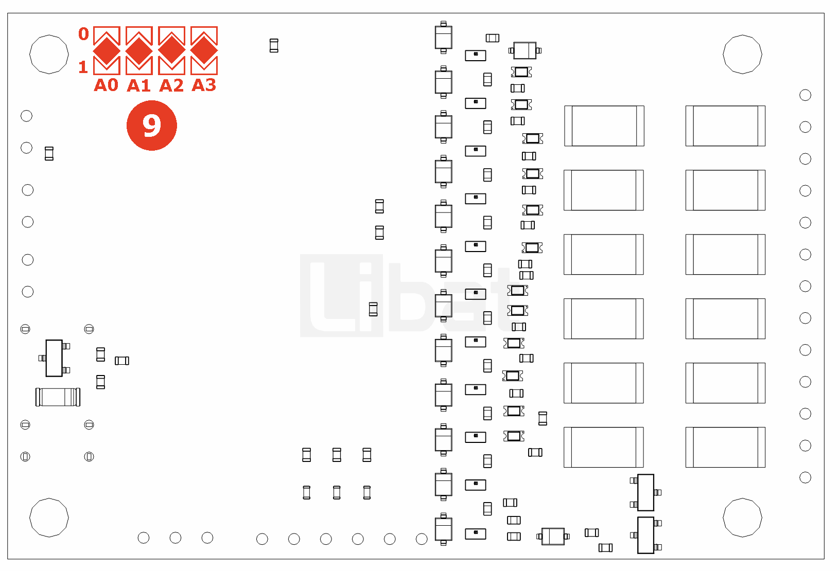
Table.2.1: Connector No#1 and #2 Descriptions
| Connector No. | Pin No. | Description (Refer the Fig.2.1 and Fig.2.2) |
|---|---|---|
| 1 or 2 | 1 | Top cell of the battery string, 12th cell's positive tab. (C12+) |
| 1 or 2 | 2 | 11th cell's positive tab. (C11+) |
| 1 or 2 | 3 | 10th cell's positive tab. (C10+) |
| 1 or 2 | 4 | 9th cell's positive tab. (C9+) |
| 1 or 2 | 5 | 8th cell's positive tab. (C8+) |
| 1 or 2 | 6 | 7th cell's positive tab. (C7+) |
| 1 or 2 | 7 | 6th cell's positive tab. (C6+) |
| 1 or 2 | 8 | 5th cell's positive tab. (C5+) |
| 1 or 2 | 9 | 4th cell's positive tab. (C4+) |
| 1 or 2 | 10 | 3rd cell's positive tab. (C3+) |
| 1 or 2 | 11 | 2nd cell's positive tab. (C2+) |
| 1 or 2 | 12 | 1st cell's positive tab. (C1+) |
| 1 or 2 | 13 | Bottom cell of the battery string. 1st cell's negative tab. (C1-) |
Table.2.2: Connector No#3 and #4 Descriptions
| Connector No. | Pin No. | Description (Refer the Fig.2.1 and Fig.2.3) |
|---|---|---|
| 3 or 4 | 1-2 | External Temperature sensor No.1 |
| 3 or 4 | 3-4 | External Temperature sensor No.2 |
| 3 or 4 | 5-6 | External Temperature sensor No.3 |
Table.2.3: Connector No#5 and #6 Descriptions
| Connector No. | Pin No. | Description (Refer the Fig.2.1 and Fig.2.3) |
|---|---|---|
| 5 or 6 | 1 | Onboard relay common pin |
| 5 or 6 | 2 | Onboard relay normally close pin |
| 6 or 6 | 3 | Onboard relay normally open pin |
Table.2.4: Connector No#7 and #8 Descriptions
| Connector No. | Pin No. | Description (Refer the Fig.2.1 and Fig.2.4) |
|---|---|---|
| 7 or 8 | 1 | Isolated daisy-chain communication port (ISO+) |
| 7 or 8 | 2 | Isolated daisy-chain communication port (ISO-) |
Table.2.5: Connector No#9 Descriptions
| Connector No. | Pin No. | Description (Refer the Fig.2.1 and Fig.2.4) |
|---|---|---|
| 9 | A0 | Board ID - 0. bit (LSB) |
| 9 | A1 | Board ID - 1. bit |
| 9 | A2 | Board ID - 2. bit |
| 9 | A3 | Board ID - 3. bit (MSB) |