4. BMS1201 Battery Connection
BMS1201 is designed for between 5S to 12S battery systems. However, user need to arrange signal and power cables for various series of battery pack. In this section, you can find the connection diagrams for 5S to 12S battery packs.
4.1 Power-Up Sequence
BMS1201 gets its own power from cell connection connector. There is no need to supply extra power and power cable for BMS. When you connect the cell connection properly, board powers on and does some inital start check. Then, it is ready to measure and communicate. If any sleep functionality is set, sometimes user may need to wake the board up after cell connection.
4.2 Cell Connection
Warning
Don't mix the power and cell voltage lines. Always separate the cell measurement ground (C1-) and power ground (B-). If you don't separate the cables from the source, unwanted sudden voltage drops may happen. This situation causes wrong cell measurements.
Warning
Always separate the top cell's positive signal (accroding to series in battery pack) and positive power output (B+). If you don't separate the cables from the source, unwanted sudden voltage drops may happen. This situation causes wrong cell measurements.
Info
User may arrange the shorted pins either on the cell measurement cable or jumpers on the board. Its up to user choice. For all type of connections, it is very important to short unused pins to highest cell of the battery pack for high quality measurements.
Fig.4.2.1: BMS1201 5S to 12S Battery Cell Connections
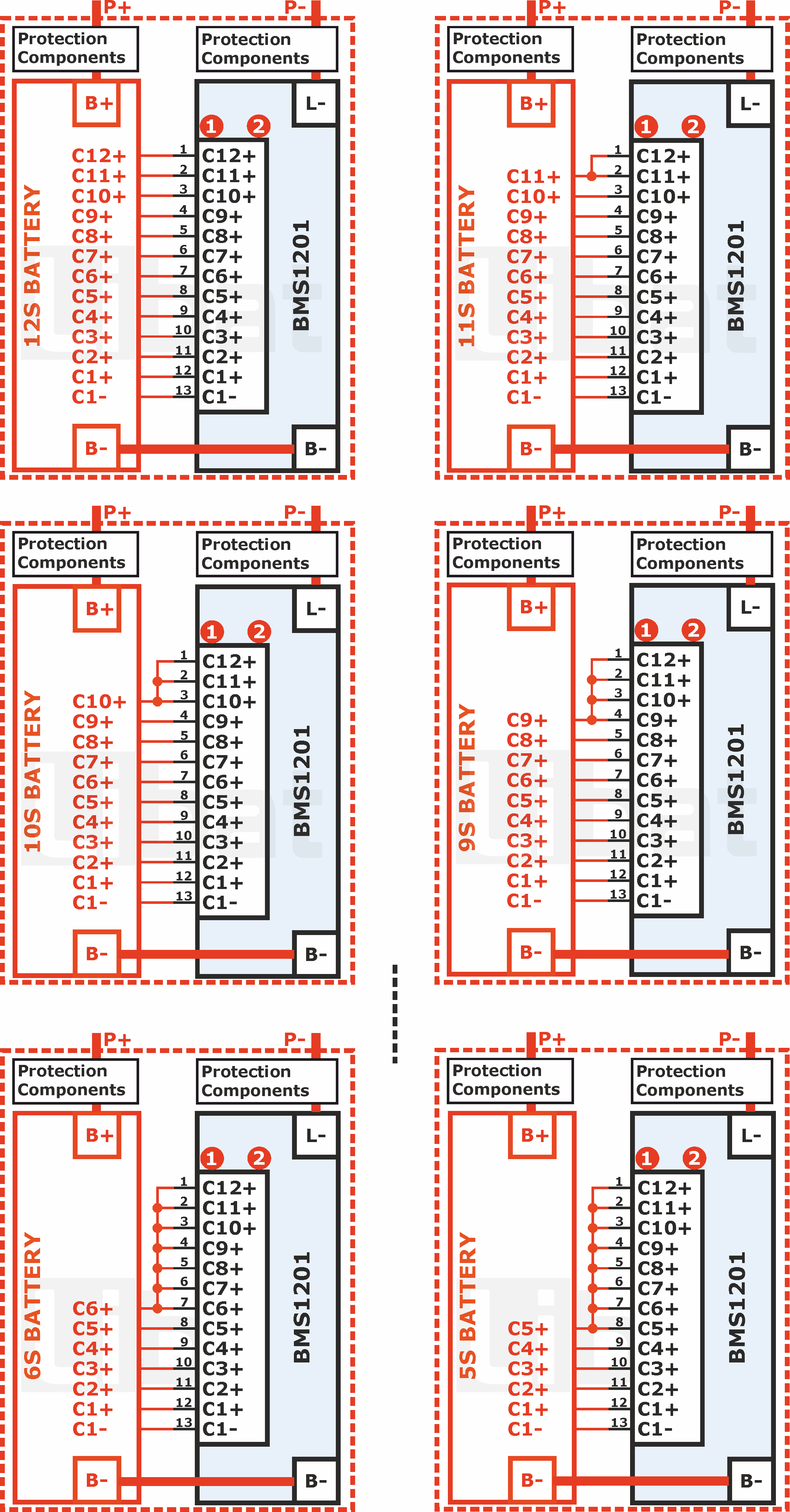
Table.4.2.1: Connection Diagrams Legend
| Name | Description |
|---|---|
| B- | Main power ground connection between BMS and BATTERY pack. Unprotected cable connection. |
| B+ | BATTERY main positive power output to the PACK's protection components. |
| L- | BMS's protection ground output. |
| P- | PACK ground output. User may place any protection components betwwen L- and P- |
| P+ | PACK positive power output. User may place any protection components betwwen B+ and P+ |
Tip
BMS1201 automatically detects how many cells connected to the board on power-up sequence. Reset after cell connection and see the connected cell count from PC software. If something goes wrong, try to fix the cables.
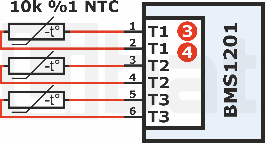
4.3 Temperature Sensor Connection
Fig.4.3.1: BMS1201 Temperature Sensor Connection
Tip
BMS1201 automatically detects how many temperature sensors connected to the board on power-up sequence. Unused pins shall short or leave float.
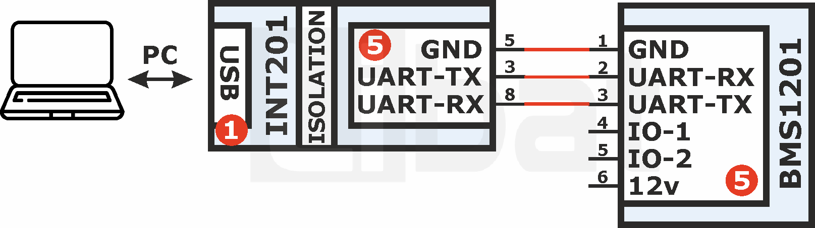
4.4 UART Connection
You can set many values and monitor the battery pack via our LiMon™ pc software by using BMS1201's uart communication. While communicating with BMS1201, you must consider BMS's the signal levels and battery's power paths every time. Below, you can see one of our isolated transceiver solution INT201 to communicate roboustly. If you want to use your own transceiver solution, make sure from returning power paths for battery commmunication, conntrolled power outputs and charger connection.
Fig.4.4.1: BMS1201 UART Connection
Warning
For connecting to BMS to your computer or another external device, it is highly recommended to use isolated communication line. Otherwise, you may damage permanently to the BMS, your computer's or remote devices's communication port.
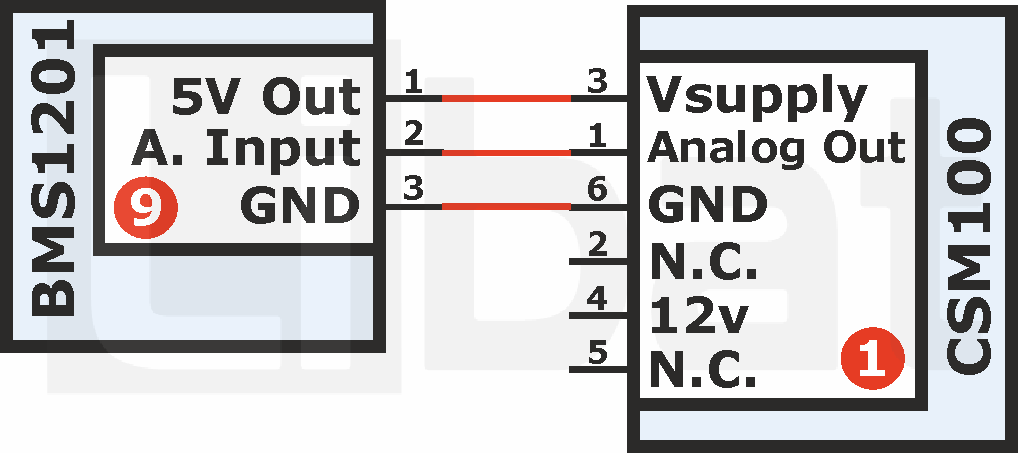
4.5 External Current Sensor Connection
You can connect external current sensors for high power applications. With a small customization you can always use CSM100 or another current sensor with proper connection.
Fig.4.5.1: BMS1201 Current Sensor Connection