2. BMS1201 Pinouts and Descriptions
On BMS1201 there are connectors for cell connections, temperature sensors, UART communication, ON/OFF button, status led and external relay board. User must arrange the cable connections to any of these connectors by guides and pinouts below. Also there are two soldering power tabs for battery ground and load ground.
Warning
There is no electrical isolation between nothing on board and connectors outputs. User must provide electrical stability for any situation. Take care for external devices in the same system with battery pack.
Warning
User must avoid the any unwanted power and signal loops to not make permanent damage any equipment.
Danger
Make sure all the connections done correctly and double check the cables. Think twice and confirm before plug into any connectors on BMS1201.
Fig.2.1: BMS1201, Board Pinout (TOP)
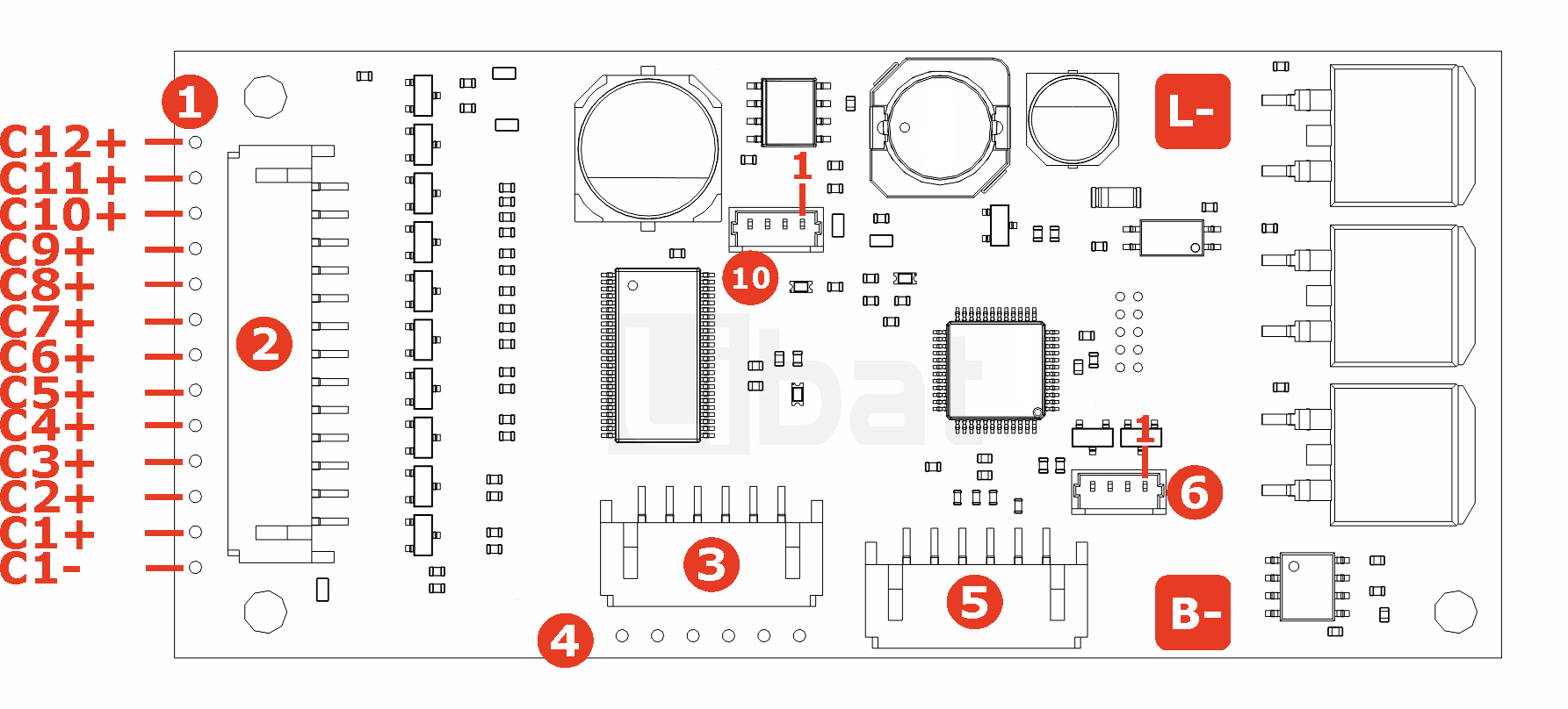
Fig.2.2: BMS1201, Board Pinout (LEFT)
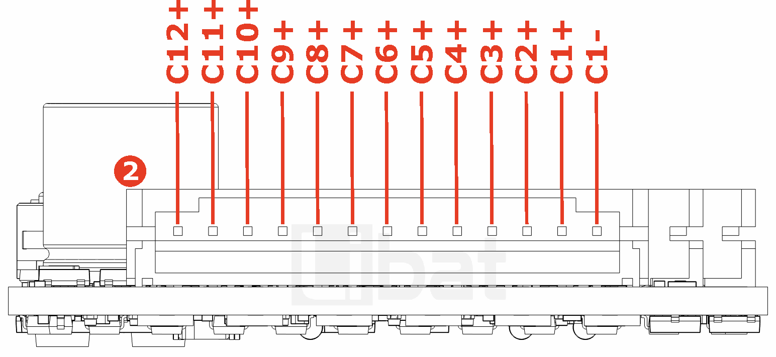
Fig.2.3: BMS1201, Board Pinout (FRONT)
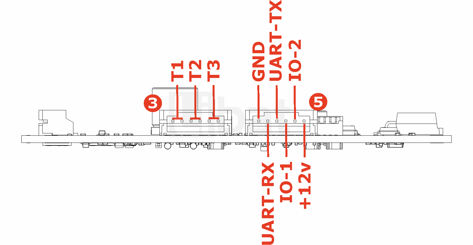
Fig.2.4: BMS1201, Board Pinout (FRONT-Alternate)
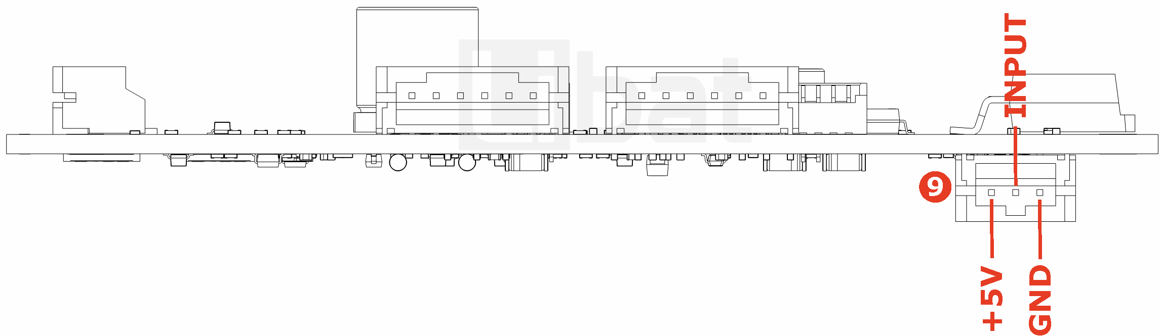
Table.2.1: Soldering TABS
| Soldering TAB | Description |
|---|---|
| B- | BATTERY Ground Connection |
| L- | LOAD Ground Connection |
Table.2.2: Connector No#1 and #2 Descriptions
| Connector No. | Pin No. | Description (Refer the Fig.2.1 and Fig.2.2) |
|---|---|---|
| 1 or 2 | 1 | Top cell of the battery string, 12th cell's positive tab. (C12+) |
| 1 or 2 | 2 | 11th cell's positive tab. (C11+) |
| 1 or 2 | 3 | 10th cell's positive tab. (C10+) |
| 1 or 2 | 4 | 9th cell's positive tab. (C9+) |
| 1 or 2 | 5 | 8th cell's positive tab. (C8+) |
| 1 or 2 | 6 | 7th cell's positive tab. (C7+) |
| 1 or 2 | 7 | 6th cell's positive tab. (C6+) |
| 1 or 2 | 8 | 5th cell's positive tab. (C5+) |
| 1 or 2 | 9 | 4th cell's positive tab. (C4+) |
| 1 or 2 | 10 | 3rd cell's positive tab. (C3+) |
| 1 or 2 | 11 | 2nd cell's positive tab. (C2+) |
| 1 or 2 | 12 | 1st cell's positive tab. (C1+) |
| 1 or 2 | 13 | Bottom cell of the battery string. 1st cell's negative tab. (C1-) |
Table.2.3: Connector No#3 and #4 Descriptions
| Connector No. | Pin No. | Description (Refer the Fig.2.1 and Fig.2.3) |
|---|---|---|
| 3 or 4 | 1-2 | External Temperature sensor No.1 |
| 3 or 4 | 3-4 | External Temperature sensor No.2 |
| 3 or 4 | 5-6 | External Temperature sensor No.3 |
Table.2.4: Connector No#5 Descriptions
| Connector No. | Pin No. | Description (Refer the Fig.2.1 and Fig.2.3) |
|---|---|---|
| 5 | 1 | GND. Same potential with bottom cell of battery string |
| 5 | 2 | UART RX for service port (Only 3.3V level) |
| 5 | 3 | UART TX for service port (Only 3.3V level) |
| 5 | 4 | General Purpose IO-1 (Only 3.3V level) |
| 5 | 5 | General Purpose IO-2 (Only 3.3V level) |
| 5 | 6 | Board DC-DC Ouptut, 12v (100mA) |
Table.2.5: Connector No#6 Descriptions
| Connector No. | Pin No. | Description (Refer the Fig.2.1) |
|---|---|---|
| 6 | - | External Relay Board Connector |
Table.2.6: Connector No#9 Descriptions
| Connector No. | Pin No. | Description (Refer the Fig.2.4) |
|---|---|---|
| 9 | 1 | 5V output |
| 9 | 2 | Analog Input |
| 9 | 3 | Ground |
Table.2.7: External On/Off Button Connector No#10 Descriptions
| Connector No. | Pin No. | Description (Refer the Fig.2.1) |
|---|---|---|
| 10 | 1 | Button Input (Battery Voltage) |
| 10 | 2 | Button Input |
| 10 | 3 | LED + |
| 10 | 4 | LED - |