2. BMS1601 Pinouts and Descriptions
On BMS1601 there are connectors for cell connections, temperature sensors, relay outputs, isolated communications and I/Os. User must arrange the cable connections to any of these connectors by guides and pinouts below. Also there are four soldering jumper points to set ID of the board.
Danger
Make sure all the connections done correctly and double check the cables. Think twice before plug into any connectors on BMS1601.
Fig.2.1: BMS1601, Board Pinout (FRONT)
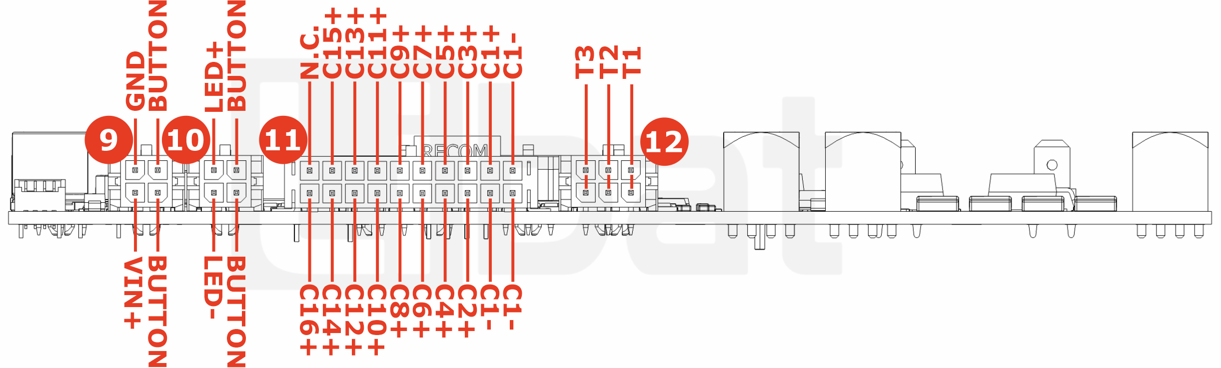
Fig.2.2: BMS1601, Board Pinout (BACK)
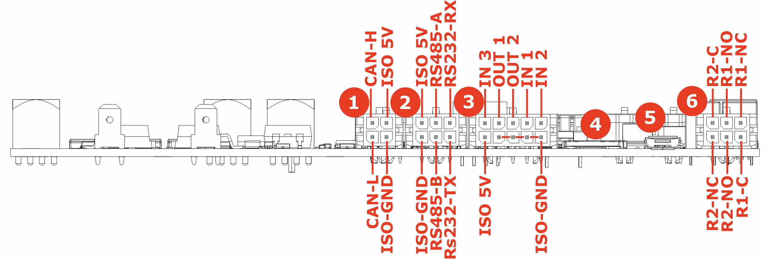
Fig.2.3: BMS1601, Board Pinout (TOP)
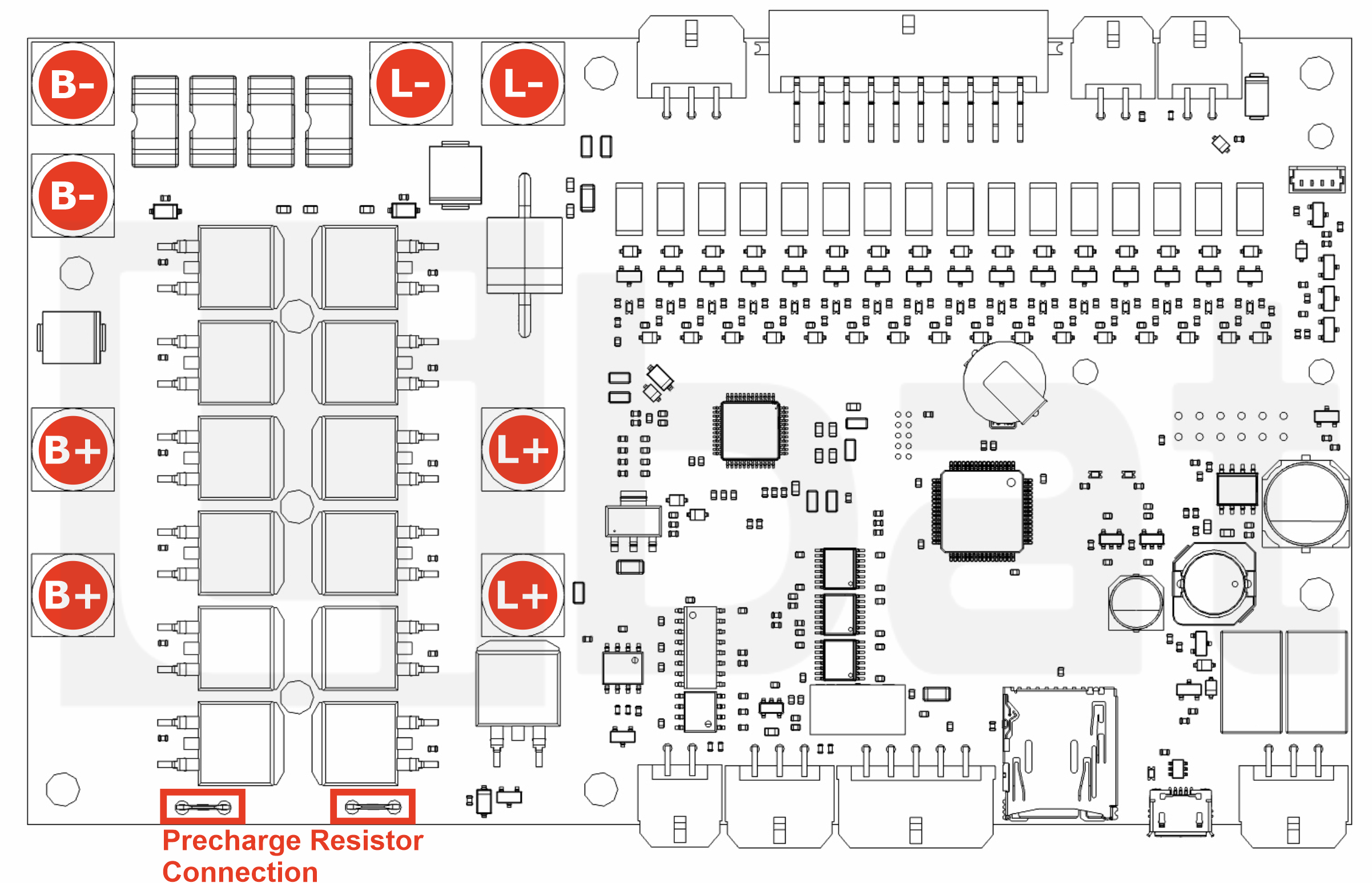
Table.2.1: Connector No#1 Descriptions
| Connector No. | Pin No. | Description (Refer the Fig.2.2) |
|---|---|---|
| 1 | 1 | CAN 2.0b LOW |
| 1 | 2 | ISO GND Output |
| 1 | 3 | ISO 5V Output |
| 1 | 4 | CAN 2.0b HIGH |
Table.2.2: Connector No#2 Descriptions
| Connector No. | Pin No. | Description (Refer the Fig.2.2) |
|---|---|---|
| 2 | 1 | RS232 No.0 Transmit Data (Service Port) |
| 2 | 2 | RS485 No.2 B Pin |
| 2 | 3 | ISO GND Output |
| 2 | 4 | RS232 No.0 Receive Data (Service Port) |
| 2 | 5 | RS485 No.2 A Pin |
| 2 | 6 | ISO 5V Output |
Table.2.3: Connector No#3 Descriptions
| Connector No. | Pin No. | Description (Refer the Fig.2.2) |
|---|---|---|
| 3 | 1 | ISO 5V Output |
| 3 | 2, 3, 4, 5 | ISO GND Output |
| 3 | 6 | ISO TTL Input 2 |
| 3 | 7 | ISO TTL Input 1 |
| 3 | 8 | ISO TTL Output 2 |
| 3 | 9 | ISO TTL Output 1 |
| 3 | 10 | ISO TTL Input 3 |
Table.2.4: Connector No#4, #5 Descriptions
| Connector No. | Pin No. | Description (Refer the Fig.2.2) |
|---|---|---|
| 4 | 1 | Micro SD Card Input (Reserved for future use) |
| 5 | 2 | Micro USB Connection (Reserved for future use) |
Table.2.5: Connector No#6 Descriptions
| Connector No. | Pin No. | Description (Refer the Fig.2.2) |
|---|---|---|
| 6 | 1 | Onboard relay No#2 normally close pin |
| 6 | 2 | Onboard relay No#2 normally open pin |
| 6 | 3 | Onboard relay No#1 common pin |
| 6 | 4 | Onboard relay No#1 normally close pin |
| 6 | 5 | Onboard relay No#1 normally open pin |
| 6 | 6 | Onboard relay No#2 common pin |
Table.2.6: Connector No#9 Descriptions
| Connector No. | Pin No. | Description (Refer the Fig.2.1) |
|---|---|---|
| 9 | 1 | Board VIN+ (Board Main Power) |
| 9 | 2 | Board VIN+ Output |
| 9 | 3 | External Button Input |
| 9 | 4 | Board GND (Board Main Power) |
Table.2.7: Connector No#10 Descriptions
| Connector No. | Pin No. | Description (Refer the Fig.2.1) |
|---|---|---|
| 10 | 1 | Board VIN+ Output |
| 10 | 2 | External Led GND Output |
| 10 | 3 | External Button Input |
| 10 | 4 | +12V Output |
Table.2.8: Connector No#11 Descriptions
| Connector No. | Pin No. | Description (Refer the Fig.2.1) |
|---|---|---|
| 11 | 1 | Top cell of the battery string, 16th cell's positive tab. (C16+) |
| 11 | 2 | 14th cell's positive tab. (C14+) |
| 11 | 3 | 12th cell's positive tab. (C12+) |
| 11 | 4 | 10th cell's positive tab. (C10+) |
| 11 | 5 | 8th cell's positive tab. (C8+) |
| 11 | 6 | 6th cell's positive tab. (C6+) |
| 11 | 7 | 4th cell's positive tab. (C4+) |
| 11 | 8 | 2th cell's positive tab. (C2+) |
| 11 | 9, 10, 11 | Bottom cell of the battery string. 1st cell's negative tab. (C1-) |
| 11 | 12 | 2nd cell's positive tab. (C1+) |
| 11 | 13 | 3rd cell's positive tab. (C3+) |
| 11 | 14 | 5th cell's positive tab. (C5+) |
| 11 | 15 | 7th cell's positive tab. (C7+) |
| 11 | 16 | 9th cell's positive tab. (C9+) |
| 11 | 17 | 11th cell's positive tab. (C11+) |
| 11 | 18 | 13th cell's positive tab. (C13+) |
| 11 | 19 | 15th cell's positive tab. (C15+) |
| 11 | 20 | No Connection |
Table.2.9: Connector No#12 Descriptions
| Connector No. | Pin No. | Description (Refer the Fig.2.1) |
|---|---|---|
| 12 | 1-2 | External Temperature sensor No.1 |
| 12 | 3-4 | External Temperature sensor No.2 |
| 12 | 5-6 | External Temperature sensor No.3 |
Table.2.3: Battery Power Connection
| Connector Name | Description (Refer the Fig.2.3) |
|---|---|
| B- | Battery Input Negative |
| B+ | Battery Input Positive |
| L- | Load Output Negative |
| L+ | Load Output Positive |
| P | Precharge Resistor Connection |