2. BMS1801 Pinouts and Descriptions
On BMS1801 there are connectors for cell connections, temperature sensors, relay output, digital communication ports, board power,on board current sensor, charge discharge FETs and I/Os. User must arrange the cable connections to any of these connectors by guides and pinouts below.
Danger
Make sure all the connections done correctly and double check the cables. Think twice before plug into any connectors on BMS1801.
Fig.2.1: BMS1801, Board Pinout (TOP)
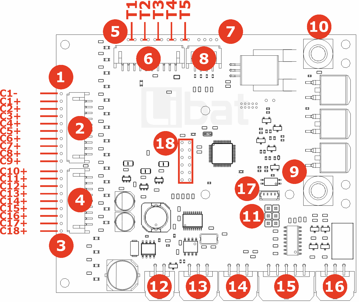
Fig.2.2: BMS1801, Board Pinout (LEFT)
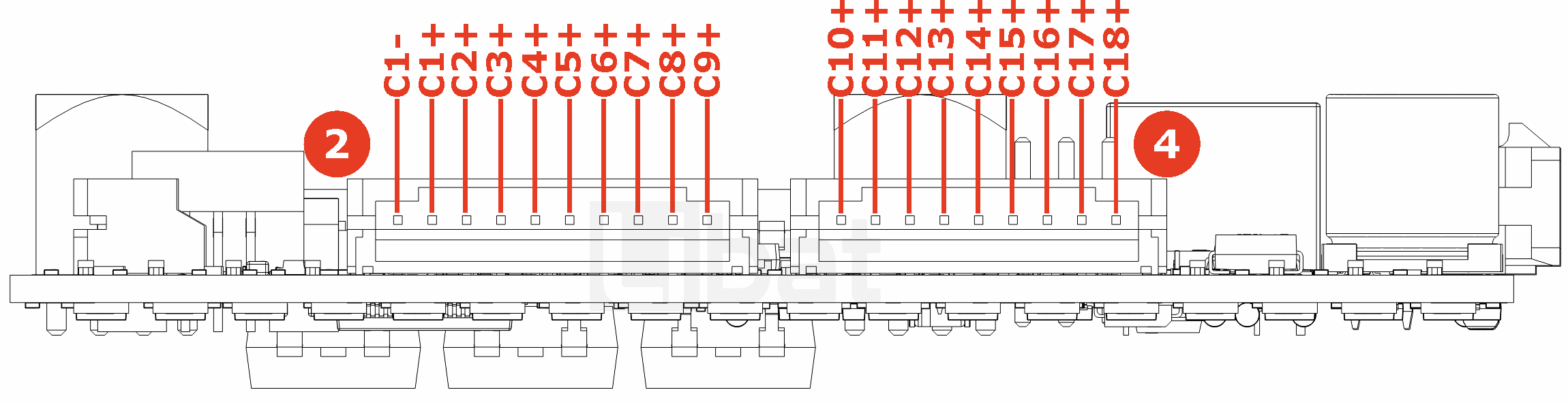
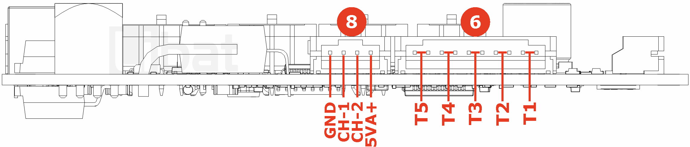
Fig.2.3: BMS1801, Board Pinout (FRONT)

Fig.2.4: BMS1801, Board Pinout (BACK)
| Connector No. | Pin No. | Description (Refer the Fig.2.1 and Fig.2.2) |
|---|---|---|
| 1 or 2 | 1 | Bottom cell of the battery string. 1st cell's negative tab. (C1-) |
| 1 or 2 | 2 | 1st cell's positive tab. (C1+) |
| 1 or 2 | 3 | 2nd cell's positive tab. (C2+) |
| 1 or 2 | 4 | 3rd cell's positive tab. (C3+) |
| 1 or 2 | 5 | 4th cell's positive tab. (C4+) |
| 1 or 2 | 6 | 5th cell's positive tab. (C5+) |
| 1 or 2 | 7 | 6th cell's positive tab. (C6+) |
| 1 or 2 | 8 | 7th cell's positive tab. (C7+) |
| 1 or 2 | 9 | 8th cell's positive tab. (C8+) |
| 1 or 2 | 10 | 9th cell's positive tab. (C9+) |
| 3 or 4 | 1 | 10th cell's positive tab. (C10+) |
| 3 or 4 | 2 | 11th cell's positive tab. (C11+) |
| 3 or 4 | 3 | 12th cell's positive tab. (C12+) |
| 3 or 4 | 4 | 13th cell's positive tab. (C13+) |
| 3 or 4 | 5 | 14th cell's positive tab. (C14+) |
| 3 or 4 | 6 | 15th cell's positive tab. (C15+) |
| 3 or 4 | 7 | 16th cell's positive tab. (C16+) |
| 3 or 4 | 8 | 17th cell's positive tab. (C17+) |
| 3 or 4 | 9 | Top cell of the battery string, 18th cell's positive tab. (C18+) |
| Connector No. | Pin No. | Description (Refer the Fig.2.1 and Fig.2.3) |
|---|---|---|
| 5 or 6 | 1-2 | External Temperature sensor No.1 |
| 5 or 6 | 3-4 | External Temperature sensor No.2 |
| 5 or 6 | 5-6 | External Temperature sensor No.3 |
| 5 or 6 | 7-8 | External Temperature sensor No.4 |
| 5 or 6 | 9-10 | External Temperature sensor No.5 |
| Connector No. | Pin No. | Description (Refer the Fig.2.1 and Fig.2.4) |
|---|---|---|
| 7 or 8 | 1 | Board Ground |
| 7 or 8 | 2 | Current Sense Channel - 1 (0-5V) |
| 7 or 8 | 3 | Current Sense Channel - 2 (0-5V) |
| 7 or 8 | 4 | 5V for Current Sensor (Don't use something else) |
| Connector No. | Pin No. | Description (Refer the Fig.2.1) |
|---|---|---|
| 9 | L- | LOAD Ground Connection |
| 10 | B- | BATTERY Ground Connection |
| 11 | - | TTL Output Voltage Source Setting |
| 17 | - | External On/Off Button Connector |
| 18 | - | Port for LiBat Extension Board |
| Connector No. | Pin No. | Description (Refer the Fig.2.1 and Fig.2.3) |
|---|---|---|
| 12 | 1 | Board VIN+ Output |
| 12 | 2 | External Led GND Output |
| 12 | 3 | External Button Input |
| 12 | 4 | +12V Output |
| Connector No. | Pin No. | Description (Refer the Fig.2.1 and Fig.2.3) |
|---|---|---|
| 13 | 1 | RS232 No.1 Transmit Data |
| 13 | 2 | Board Ground |
| 13 | 3 | CAN 2.0b Low Pin |
| 13 | 4 | RS232 No.1 Receive Data |
| 13 | 5 | +12V Output |
| 13 | 6 | CAN 2.0b High Pin |
| Connector No. | Pin No. | Description (Refer the Fig.2.1 and Fig.2.3) |
|---|---|---|
| 14 | 1 | RS232 No.0 Transmit Data (Service Port) |
| 14 | 2 | RS485 No.2 B Pin |
| 14 | 3 | Board Ground |
| 14 | 4 | RS232 No.0 Receive Data (Service Port) |
| 14 | 5 | RS485 No.2 A Pin |
| 14 | 6 | +12V Output |
| Connector No. | Pin No. | Description (Refer the Fig.2.1 and Fig.2.3) |
|---|---|---|
| 15 | 1, 2, 3, 4 | Board Ground |
| 15 | 5 | +12V Output |
| 15 | 6 | TTL Input - 2 (0-5V) |
| 15 | 7 | TTL Input - 1 (0-5V) |
| 15 | 8 | TTL Output - 2 (Normally 0-5V but may vary on Con.No.6 settings) |
| 15 | 9 | TTL Output - 1 (Normally 0-5V but may vary on Con.No.6 settings) |
| 15 | 10 | External Voltage Source for TTL Outputs |
| Connector No. | Pin No. | Description (Refer the Fig.2.1 and Fig.2.3) |
|---|---|---|
| 16 | 1 | Relay 1 Common Pin |
| 16 | 2 | Open Drain Output No.2 |
| 16 | 3 | Open Drain Output No.1 |
| 16 | 4 | Relay 1 Normally Closed Pin |
| 16 | 5 | Relay 1 Normally Open Pin |
| 16 | 6 | Board Ground |