2. BMS1802 Pinouts and Descriptions
Introducing the LiBat™ BMS1802, a revolutionary daisy-chain slave device designed exclusively for 5S-18S lithium battery packs. Engineered for energy storage and mobility applications, this Battery Management System (BMS) sets new standards in efficiency and precision for battery control. As a dedicated slave unit, the BMS1802 seamlessly integrates into lithium battery configurations, offering a comprehensive solution for monitoring and managing power in various applications.
The BMS1802 boasts advanced features and adaptability, making it a pivotal component in optimizing the performance and safety of lithium battery packs. It is easy to use with no hardware configuration required, providing a plug-and-play solution with no software configuration needed. The device facilitates 5S-18S cell measurement with 0.1mV resolution, adjustable passive balancing current up to 1A, and auto deep sleep functionality.
Key features also include a 1.5kV isolated daisy-chain communication line, self-powering capability, and a combination of 5 external and 3 internal NTC sensors. The BMS1802 is equipped with LEDs for balancing and status indicators, ensuring clear visual feedback. Utilizing standard CAT-5 patch cables for daisy-chain connectivity, this innovative device heralds the future of battery management, where reliability and innovation converge to enhance energy solutions. Embrace the future with BMS1802 and redefine the way you manage lithium battery packs.
Danger
Make sure all the connections done correctly and double check the cables. Think twice before plug into any connectors on BCU2002.
Fig.2.1: BMS1802, Board Pinout (TOP)
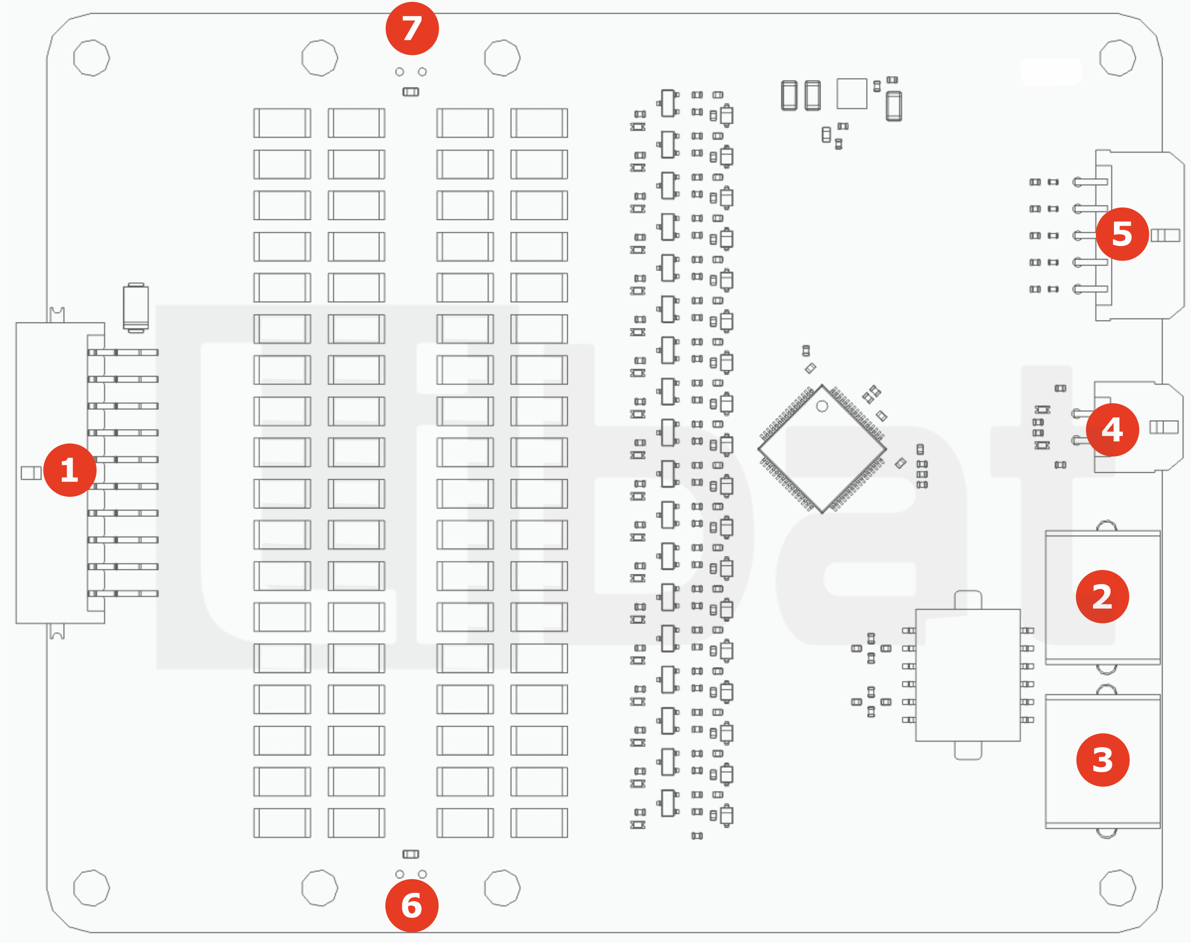
Fig.2.2: BMS1802, Board Pinout (LEFT)
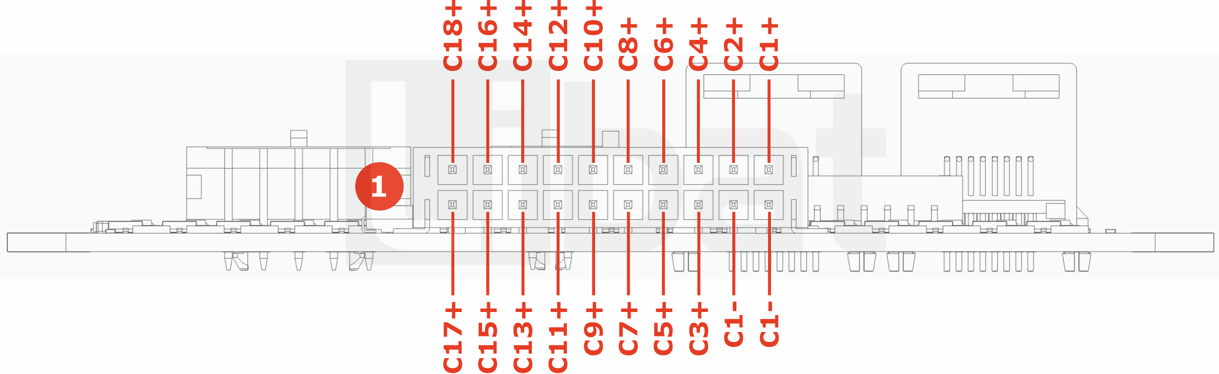
Fig.2.3: BMS1802, Board Pinout (RIGHT)
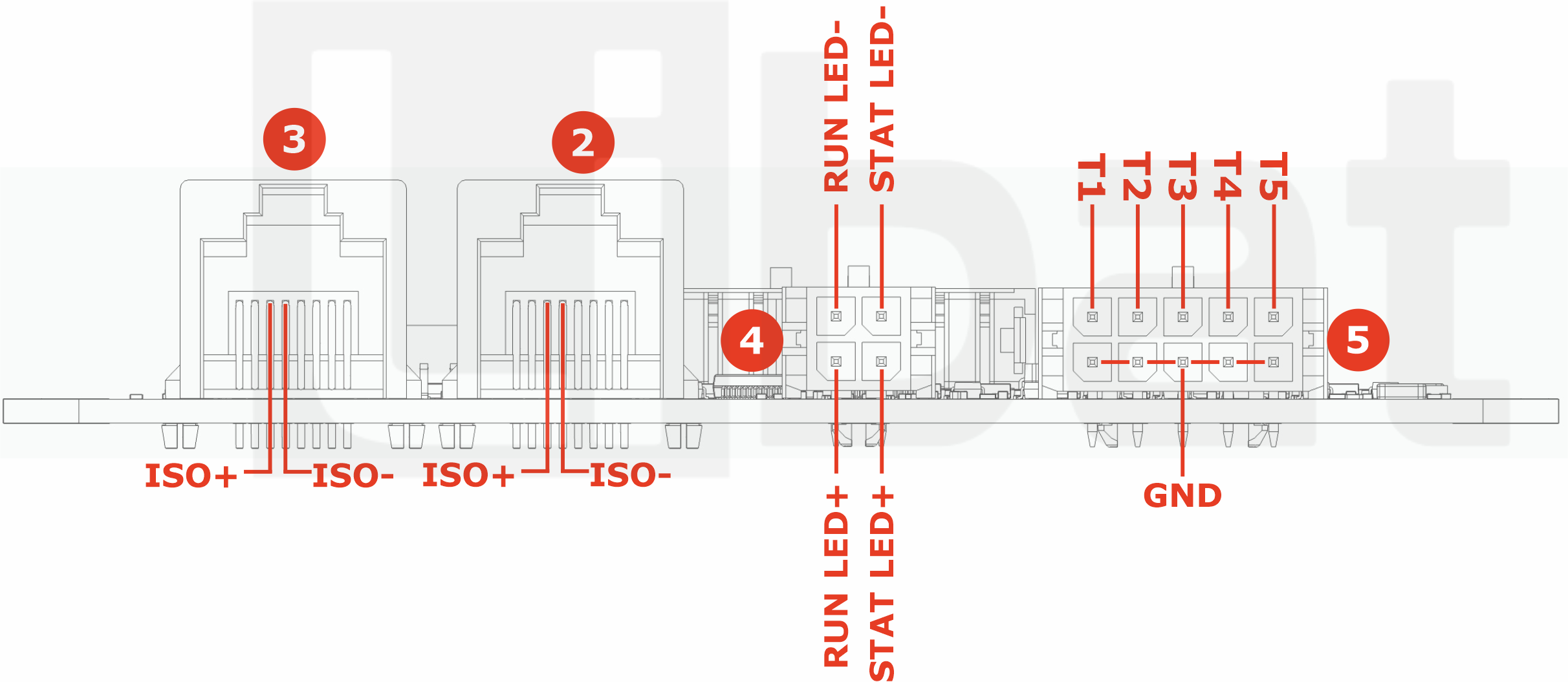
Table.2.1: Connector No#1 Descriptions
| Connector No. | Pin No. | Description (Refer the Fig.2.1 and Fig.2.2) |
|---|---|---|
| 1 | 1 | Bottom cell of the battery string. 1st cell's negative tab. (C1-) |
| 1 | 2 | Bottom cell of the battery string. 1st cell's negative tab. (C1-) |
| 1 | 3 | 3rd cell's positive tab. (C3+) |
| 1 | 4 | 5th cell's positive tab. (C5+) |
| 1 | 5 | 7th cell's positive tab. (C7+) |
| 1 | 6 | 9th cell's positive tab. (C9+) |
| 1 | 7 | 11th cell's positive tab. (C11+) |
| 1 | 8 | 13th cell's positive tab. (C13+) |
| 1 | 9 | 15th cell's positive tab. (C15+) |
| 1 | 10 | 17th cell's positive tab. (C17+) |
| 1 | 11 | 1st cell's positive tab. (C1+) |
| 1 | 12 | 2nd cell's positive tab. (C2+) |
| 1 | 13 | 4th cell's positive tab. (C4+) |
| 1 | 14 | 6th cell's positive tab. (C6+) |
| 1 | 15 | 8th cell's positive tab. (C8+) |
| 1 | 16 | 10th cell's positive tab. (C10+) |
| 1 | 17 | 12th cell's positive tab. (C12+) |
| 1 | 18 | 14th cell's positive tab. (C14+) |
| 1 | 19 | 16th cell's positive tab. (C16+) |
| 1 | 20 | Top cell of the battery string, 18th cell's positive tab. (C18+) |
Table.2.2: Connector No#2, #3 Descriptions
| Connector No. | Pin No. | Description (Refer the Fig.2.1 and Fig.2.3) |
|---|---|---|
| 2 | - | RJ45 Daisy-Chain Communication OUTPUT Port (1.5kV Isolated) |
| 3 | - | RJ45 Daisy-Chain Communication INPUT Port (1.5kV Isolated) |
Table.2.3: Connector No#4 Descriptions
| Connector No. | Pin No. | Description (Refer the Fig.2.1 and Fig.2.3) |
|---|---|---|
| 4 | 1 | Positive Pin of RUN LED (no external resistor need) |
| 4 | 2 | Positive Pin of STAT LED (no external resistor need) |
| 4 | 3 | Negative Pin of RUN LED (no external resistor need) |
| 4 | 4 | Negative Pin of STAT LED (no external resistor need) |
Table.2.4: Connector No#5 Descriptions
| Connector No. | Pin No. | Description (Refer the Fig.2.1 and Fig.2.3) |
|---|---|---|
| 5 | 1,2,3,4,5 | GND for temperature sensors |
| 5 | 6 | External Temperature sensor No#1 |
| 5 | 7 | External Temperature sensor No#2 |
| 5 | 8 | External Temperature sensor No#3 |
| 5 | 9 | External Temperature sensor No#4 |
| 5 | 10 | External Temperature sensor No#5 |
Table.2.5: Connector No#6, #7 Descriptions
| Connector No. | Pin No. | Description (Refer the Fig.2.1) |
|---|---|---|
| 6 | - | Internal Temperature sensor No#1 |
| 7 | - | Internal Temperature sensor No#2 |