1.1. Canbus Introduction
The CAN bus was developed by BOSCH as a multi-master, message broadcast system that specifies a maximum signaling rate of 1 megabit per second (bps). Unlike a traditional network such as USB or Ethernet, CAN does not send large blocks of data point-to-point from node A to node B under the supervision of a central bus master. In a CAN network, many short messages like temperature or RPM are broadcast to the entire network, which provides for data consistency in every node of the system. Once CAN basics such as message format, message identifiers, and bit-wise arbitration -- a major benefit of the CAN signaling scheme are explained, a CAN bus implementation is examined, typical waveforms presented, and transceiver features examined.
CAN is an International Standardization Organization (ISO) defined serial communications bus originally developed for the automotive industry to replace the complex wiring harness with a two-wire bus. The specification calls for high immunity to electrical interference and the ability to self-diagnose and repair data errors. These features have led to CAN's popularity in a variety of industries including building automation, medical, and manufacturing. The CAN communications protocol, ISO-11898: 2003, describes how information is passed between devices on a network and conforms to the Open Systems Interconnection (OSI) model that is defined in terms of layers. Actual communication between devices connected by the physical medium is defined by the physical layer of the model.
Signaling is differential which is where CAN derives its robust noise immunity and fault tolerance. Balanced differential signaling reduces noise coupling and allows for high signaling rates over twisted-pair cable. Balanced means that the current flowing in each signal line is equal but opposite in direction, resulting in a field-canceling effect that is a key to low noise emissions. The use of balanced differential receivers and twisted-pair cabling enhance the common-mode rejection and high noise immunity of a CAN bus.
Fig.1.1.1: Details of a CAN Bus
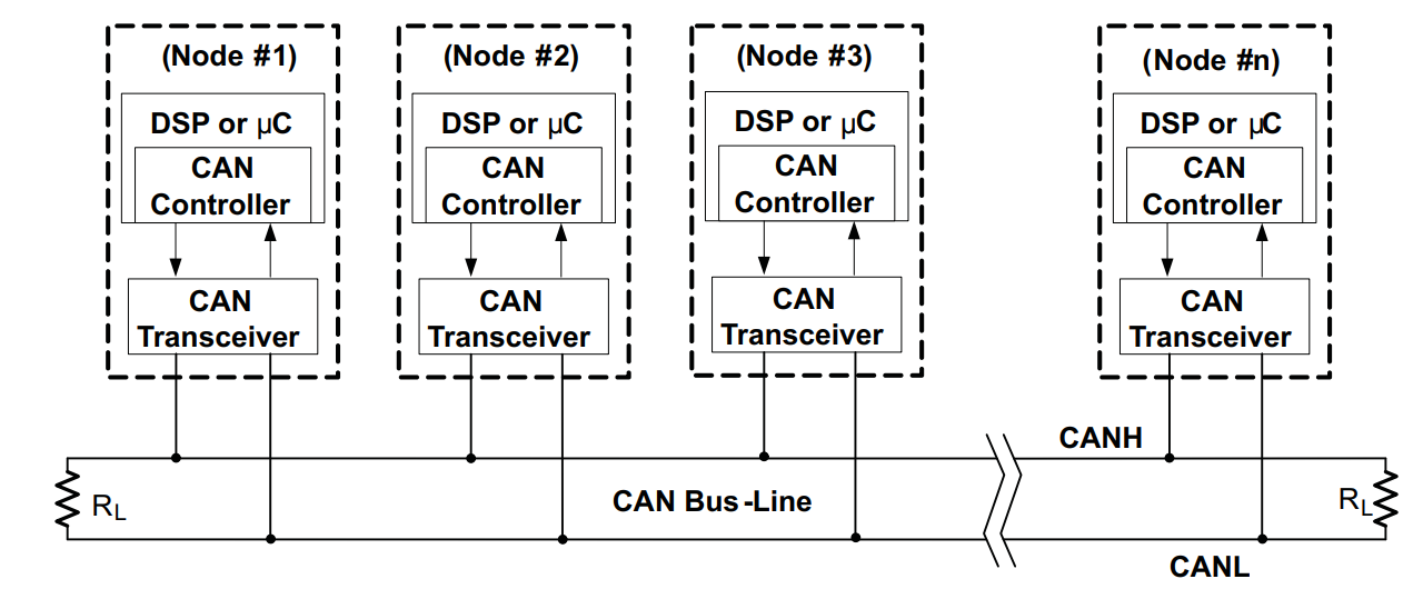
The High-Speed ISO 11898 Standard specifications are given for a maximum signaling rate of 1 Mbps with a bus length of 40 meters with a maximum of 30 nodes. It also recommends a maximum unterminated stub length of 0.3 meter. The cable is specified to be a shielded or unshielded twisted-pair with a 120-Ω characteristic impedance (Zo). The ISO 11898 Standard defines a single line of twisted-pair cable as the network topology as shown in Fig.1.1, terminated at both ends with 120-Ω resistors, which match the characteristic impedance of the line to prevent signal reflections. According to ISO 11898, placing RL on a node must be avoided because the bus lines lose termination if the node is disconnected from the bus.
As a conclusion, for a good communication always pay your attention to points below,
- The CAN bus must be a single bus (NOT star or ring) with short stubs. Maximum stub length is 50 cm, recommended stub length 30 cm.
- The CAN cable must be well shielded.
- CAN H and CAN L must be twisted, at least 40 turns per meter.
- The CAN bus must be terminated with a 120-Ω resistor at both ends.
- The CAN bus must be kept as far away as possible from any high voltage cables, minimum 30 cm.
- All high voltage cables must be well shielded.
Note
For more detailed information about can bus physical layer, we highly recommend to read this article. ARTICLE: Controller Area Network Canbus Physical Layer and Bus Topology