2.1. Modbus Introduction
In 1979, Modicon introduced an application layer protocol (layer 7 of the OSI model) for use with its Programmable Logic Controllers (PLC). This protocol was called Modbus and became the first widely used fieldbus in the history of automation. A fieldbus is a communication protocol used in industrial networks to connect field devices to industrial controllers. A fieldbus often reduces the amount of wiring needed between controllers and devices because multiple devices can connect to the same pair of wires. There are a number of popular fieldbus technologies out there including Modbus, Profibus, Foundation Fieldbus, ControlNet, DeviceNet, and many others.
Modbus was designed to connect field devices to industrial controllers. At the time of its invention, most devices used voltage or current representations as a means to communicate the device's state. This meant high or low bits for discrete control and 0-10V or 4-20mA for analog control. The slow transition to fieldbus technologies resulted in Modbus being one of the simplest protocols with new versions being added over the years. Originally, Modbus was implemented over a serial communication link, i.e., RS-232/RS-485. Eventually, the protocol was adapted for use over TCP/IP and Ethernet. This is commonly referred to as Modbus TCP.
Classic Modbus has two transmission modes: ASCII and RTU. In ASCII mode, data is sent as the ASCII characters 0-9 and A-F, while in RTU mode, data is represented in 8-bit binary. Data and addresses are encoded in big-endian, resulting in the most significant byte being transmitted first.
Modbus data comes in four primary types:
- Discrete inputs
- Coils (outputs)
- Input registers
- Holding registers
Discrete inputs represent a single bit of data and are read-only. Coils also represent a single bit but can be both read and written to. Input registers represent 16-bit read-only data, while holding registers are 16-bit read-write data. Figure 1.1.1 summarizes this.
Fig.2.1.1: Details of a modbus
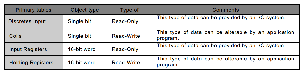
For each type, a maximum of 2^16 (65536) data items can be located in a device's memory. There are specific function codes for accessing each of the different data types, with each type often having its own dedicated block of memory. To address a data item, a master simply uses the range from 0-65535. Data item 1 would be located at address 0x0000. Data item 2 would be at address 0x0001. Data item 65536 would be found at 0xFFFF. Keep in mind devices aren't required to have all 65536 data items it's simply the maximum.
With an understanding of how data is represented in Modbus, it is possible to look at a transaction in detail. This will be from the perspective of the PDU, since the PDU is communication-layer-independent. The Modbus specification defines three types of PDUs:
- Modbus Request
- Modbus Response
- Modbus Exception Response
The master initiates a request by using the function code, while the slave sends a response in reaction to that request. A successful response echoes the function code sent to it by the master. An exception response replies with the same function code but with the msb (most significant bit) set high to indicate something went wrong.
There are a number of function codes defined by the Modbus specification. Function code 0x01 is the Read Coils function.
Figure 2.1.2 shows an example of what a Read Coils request and response might look like. The Modbus master sends a request with function code 0x01 (Read Coils) starting at the first data item (address 0x0000) and reading only a single coil. The Read Coils function can be used to read up to 2000 (0x7D0) coils at once.
Fig.2.1.2: Read Coils Transaction
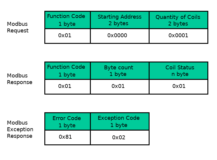
If successful, the slave responds with the same function code and a count of the number of coils it's replying with. The coil status will be n bytes wide with each bit representing whether that particular coil is ON (1) or OFF (0).
In this case, the coil at address 0x0000 is ON. Had the request not been successful, the exception response would contain the function code with the msb set high (0x81) along with an exception code that explains what went wrong. Exception code 0x02 means that an illegal data address was used, i.e., there is no coil at 0x0000 in this slave's memory.
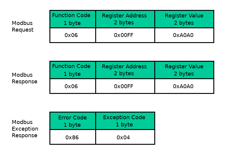
Figure 5 shows an example of a Write Single Register transaction (function code 0x06). Here, the master requests a write of data 0xA0A0 to address 0x00FF. The slave's response is simply an echo of the request.
The example exception response here shows the function code with the msb set high along with an exception code of 0x04. This code means that an unrecoverable error has occurred while the slave was attempting to perform the request.
Fig.2.1.3: Write Single Register Transaction
All Modbus function codes follow a similar pattern to the two examples shown above.
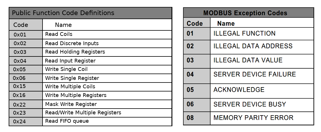
Figure 2.1.4 shows a list of the common function codes along with exception codes for exception responses. For more information consult the Modbus specification.
Fig.2.1.4: Function Codes and Exception Codes