2. CSM100 Pinouts and Descriptions
On CSM100 there are connectors for main power path and sensor input/outpus.
Note
You may place current sensor any current way. If you use bidirectional sensor with same absolute current ratings, you can set the right current way via our configuration tool.
Fig.2.1: CSM100, Board Pinout (TOP)
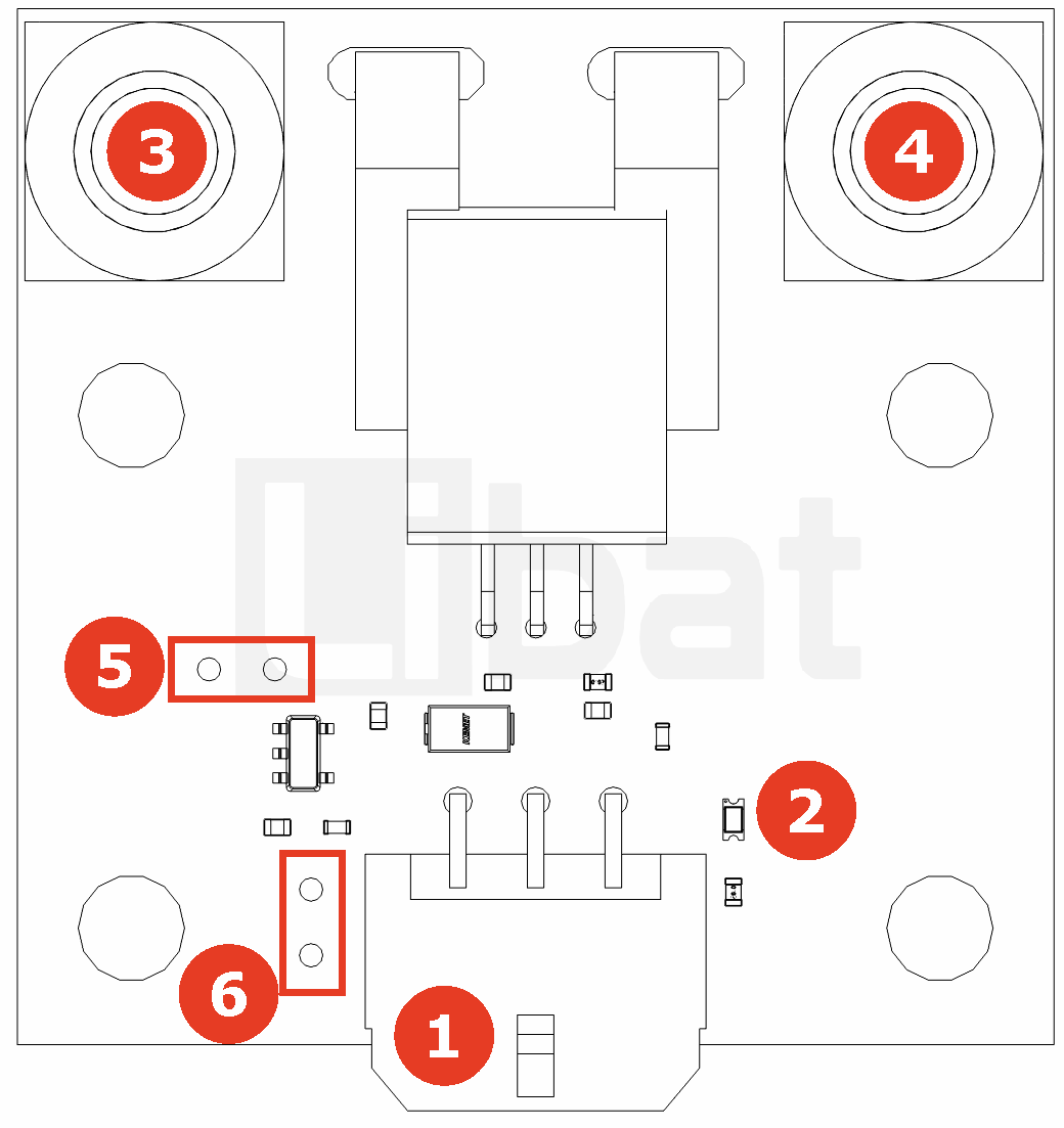
Fig.2.2: CSM100, Board Pinout (FRONT)
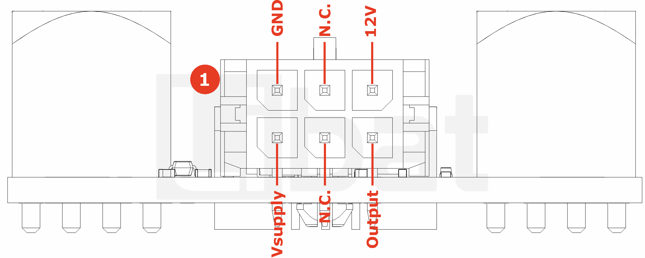
Table.2.1: Connector No#1 Descriptions
| Connector No# | Pin No. | Description (Refer the Fig.2.1) |
|---|---|---|
| 1 | 1 | Analog Output |
| 1 | 2 | No Connection (N.C.) |
| 1 | 3 | Board Power Supply |
| 1 | 4 | 12V input (Not for supply) |
| 1 | 5 | No Connection (N.C.) |
| 1 | 6 | Ground |
Table.2.2: Connector No# 2,3,4,5,6 Descriptions
| Connector No# | Pin No. | Description (Refer the Fig.2.2) |
|---|---|---|
| 2 | - | Power Status LED |
| 3 | - | Main Power Path Connection |
| 4 | - | Main Power PAth Connection |
| 5 | - | 3.3V - Vsupply Selection |
| 6 | - | Power Status LED Source Selection (Vsupply or 12V) |