2. DIS100 Pinouts and Descriptions
On DIS100 there are connectors for TTL UART, external LED and user button. User must arrange the cable connections to any of these connectors by guides and pinouts below.
Warning
Make sure the voltage levels of pins and input-output status to connect to any external device.
Fig.2.1: DIS100, Board Pinout (TOP)
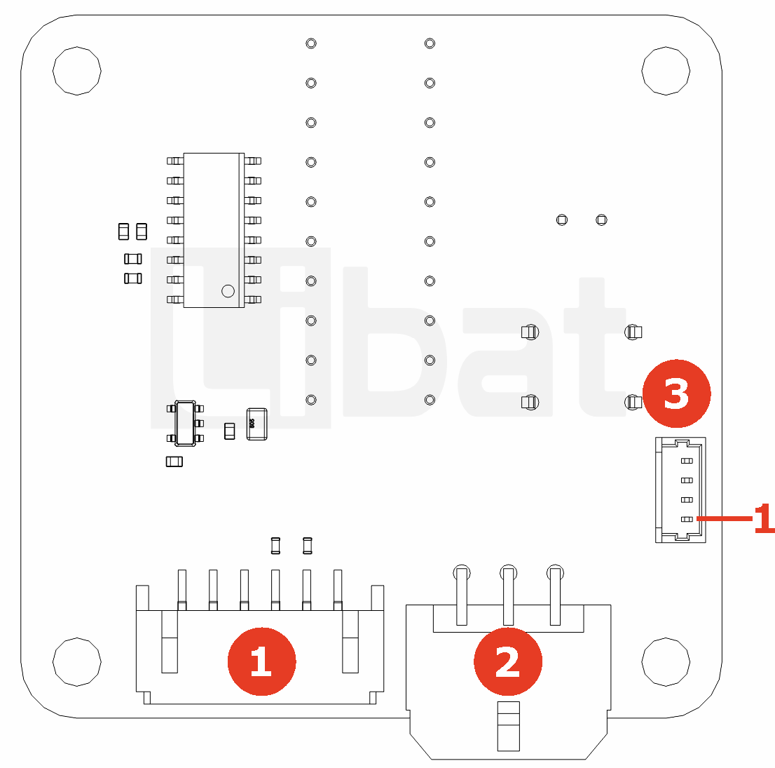
Fig.2.2: DIS100, Board Pinout (BOTTOM)
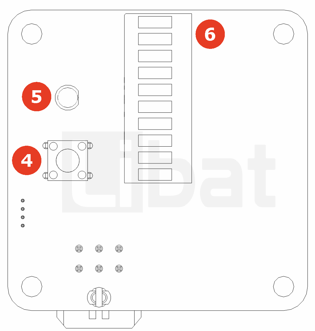
Fig.2.3: DIS100, Board Pinout (RIGHT)
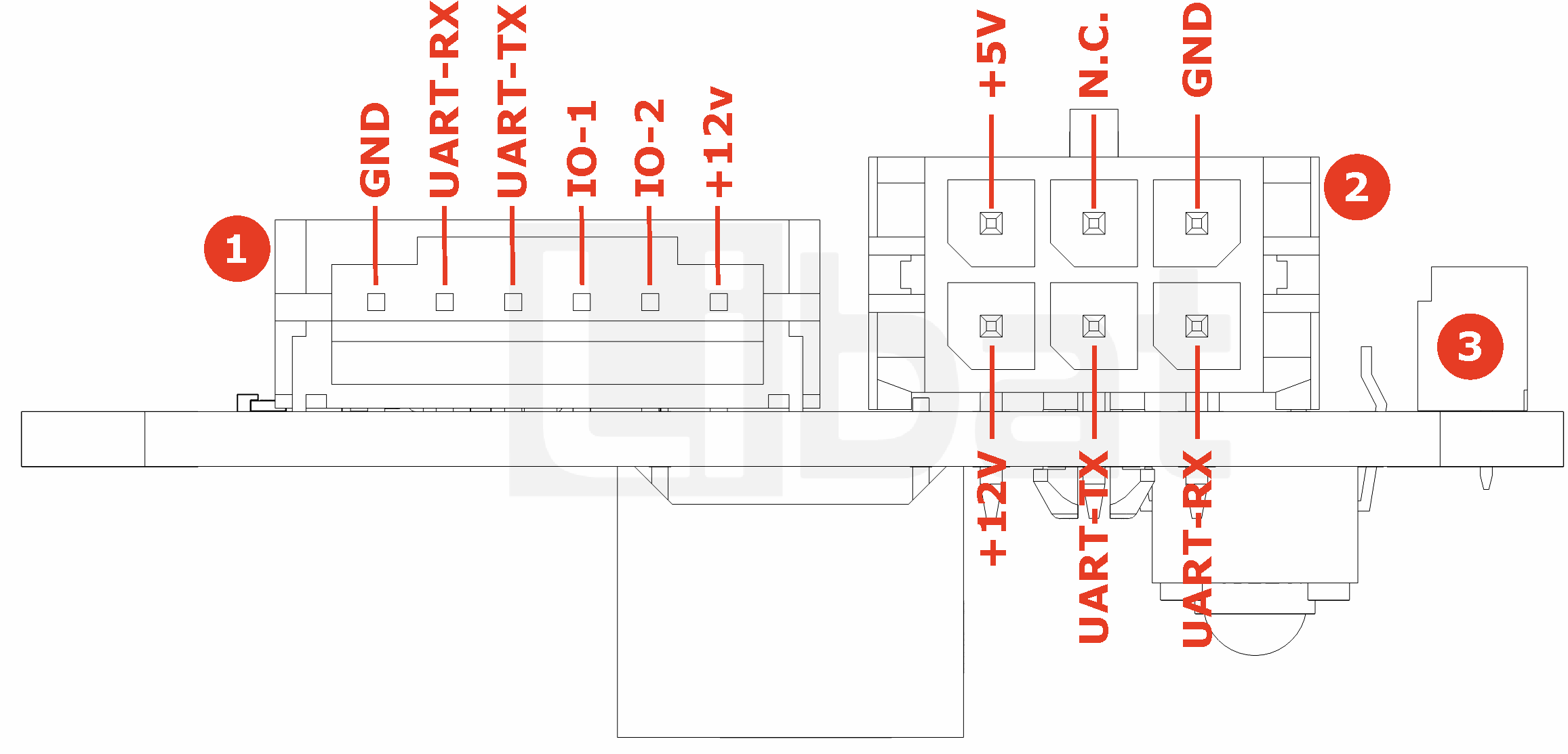
Table.2.1: Connector No# 1 Descriptions
| Connector No# | Pin No. | Description (Refer the Fig.2.3) |
|---|---|---|
| 1 | 1 | GND. Same potential with bottom cell of battery string |
| 1 | 2 | UART RX for service port (Only 3.3V level) |
| 1 | 3 | UART TX for service port (Only 3.3V level) |
| 1 | 4 | General Purpose IO-1 (Only 3.3V level) |
| 1 | 5 | General Purpose IO-2 (Only 3.3V level) |
| 1 | 6 | Board Power Supply, 12V |
Table.2.2: Connector No# 2 Descriptions
| Connector No# | Pin No. | Description (Refer the Fig.2.3) |
|---|---|---|
| 1 | 1 | UART RX for service port (Only 3.3V level) |
| 1 | 2 | UART TX for service port (Only 3.3V level) |
| 1 | 3 | Board Power Supply, 12V |
| 1 | 4 | GROUND |
| 1 | 5 | No Connection |
| 1 | 6 | Board Power Output, 5V (100mA) |
Table.2.3: Connector No# 3 Descriptions
| Connector No# | Pin No. | Description (Refer the Fig.2.1) |
|---|---|---|
| 3 | 1 | Button Input |
| 3 | 2 | Button Input |
| 3 | 3 | LED + |
| 3 | 4 | LED - |
Table.2.4: Connector No# 4,5,6 Descriptions
| Connector No# | Pin No. | Description (Refer the Fig.2.2) |
|---|---|---|
| 4 | - | User Button |
| 5 | - | Status LED |
| 6 | - | LED Bar Graph |