2. INT201 Pinouts and Descriptions
On INT201 there are connectors for USB and serial outputs, dip switch for selecting serial channel. User must arrange the cable connections to any of these connectors by guides and pinouts below.
Warning
Make sure the PC driver is installed and working properly. Please check the device manager (or equvaliant) to see port name.
Fig.2.1: INT201, Board Pinout (TOP)
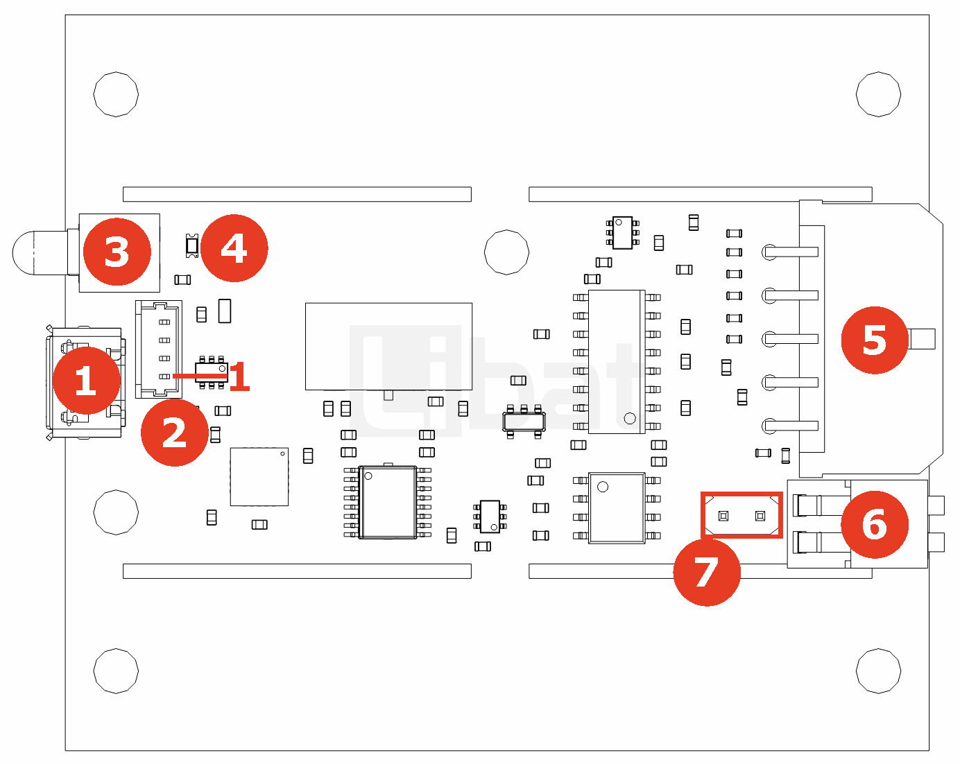
Fig.2.2: INT201, Board Pinout (RIGHT)
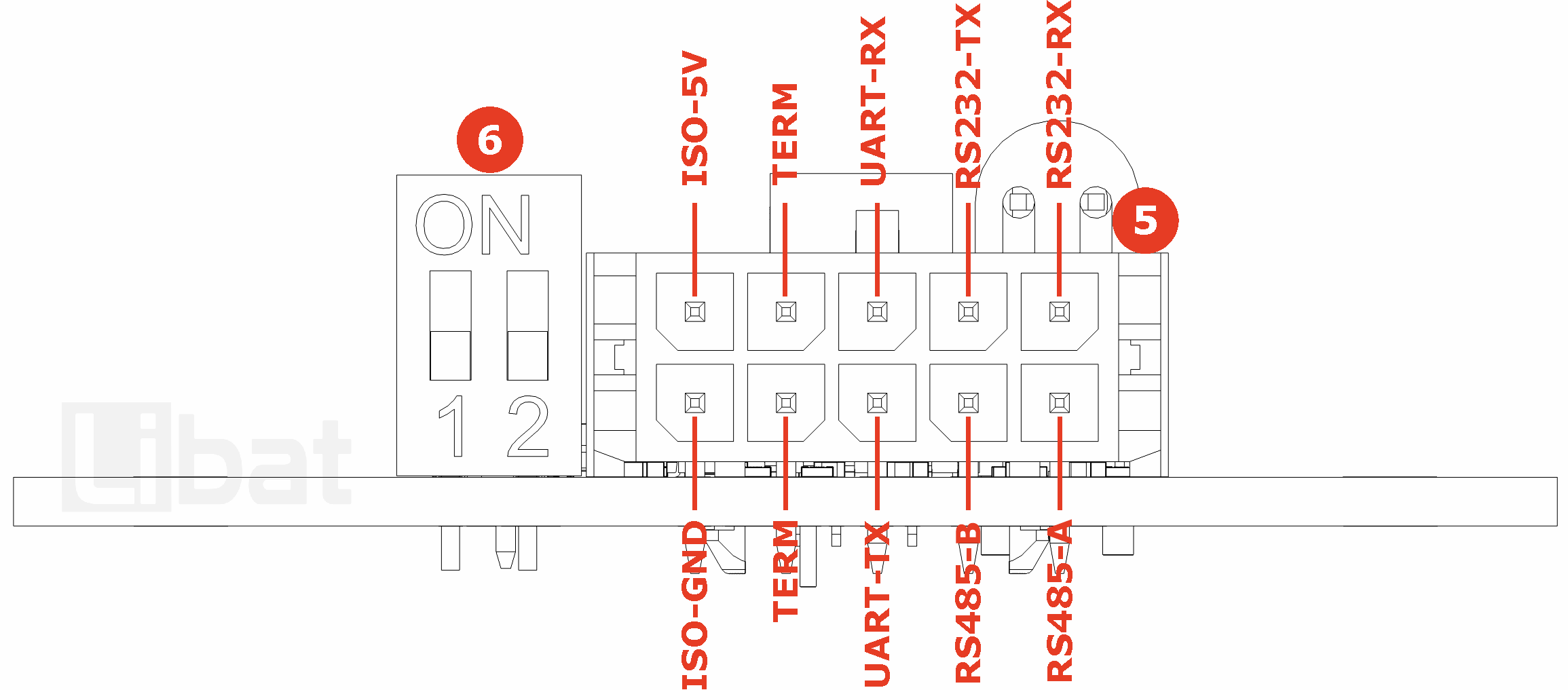
Table.2.1: Connector No# 1, 2 3, 4 and 7 Descriptions
| Connector No# | Pin No. | Description (Refer the Fig.2.1) |
|---|---|---|
| 1 | - | Micro USB Type B, USB 2.0 Connector |
| 2 | 1 | USB GND |
| 2 | 2 | USB Data+ |
| 2 | 3 | USB Data- |
| 2 | 4 | USB +5v |
| 3 | - | Status LED (THT) |
| 4 | - | Status LED (SMD) |
| 7 | - | RS485 termination jumper |
Table.2.2: Connector No# 5 Descriptions
| Connector No# | Pin No. | Description (Refer the Fig.2.1 and Fig.2.2) |
|---|---|---|
| 5 | 1 | RS485 B |
| 5 | 2 | RS485 A |
| 5 | 3 | UART Transmit Data (TTL Level, 3.3v - 5V) |
| 5 | 4 | RS485 Termination (Short to Pin#9) |
| 5 | 5 | Isolated GND (Only Output) |
| 5 | 6 | RS232 Receive Data Pin |
| 5 | 7 | RS232 Transmit Data Pin |
| 5 | 8 | UART Recevice Data (TTL Level, 3.3v - 5V) |
| 5 | 9 | RS485 Termination (Short to Pin#5) |
| 5 | 10 | Isolated 5V (Only Output) |
Table.2.3: Connector No# 6 Descriptions
| Connector No# | SW No#1 | SW No#2 | Description (Refer the Fig.2.1 and Fig.2.2) |
|---|---|---|---|
| 6 | OFF | OFF | RS232 Mode |
| 6 | ON | OFF | RS485 Mode |
| 6 | OFF | ON | UART Mode |
| 6 | ON | ON | DO NOT USE |